
Hinge for expandable solar cell array of cubesat
A solar cell array and CubeSat technology, applied in the direction of pivot connection, etc., can solve the problems of increased launch cost, poor portability, and less power generation, and achieves reduced launch cost, good irradiation effect, and good portability. Effect
- Summary
- Abstract
- Description
- Claims
- Application Information
AI Technical Summary
Problems solved by technology
Method used
Image

Examples
Embodiment
[0027] combine Figure 1 to Figure 5 :
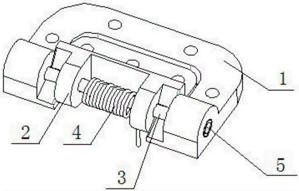
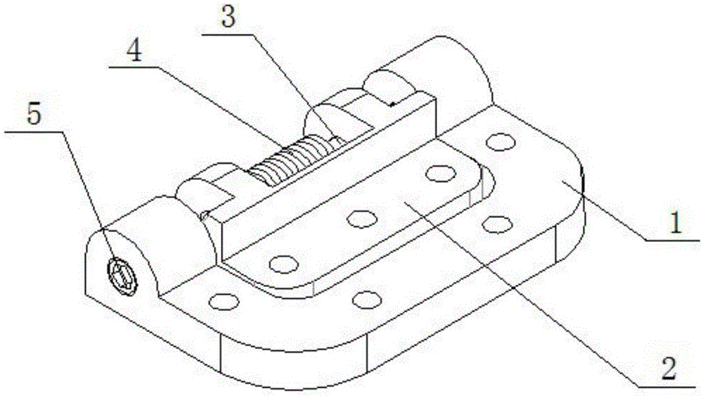
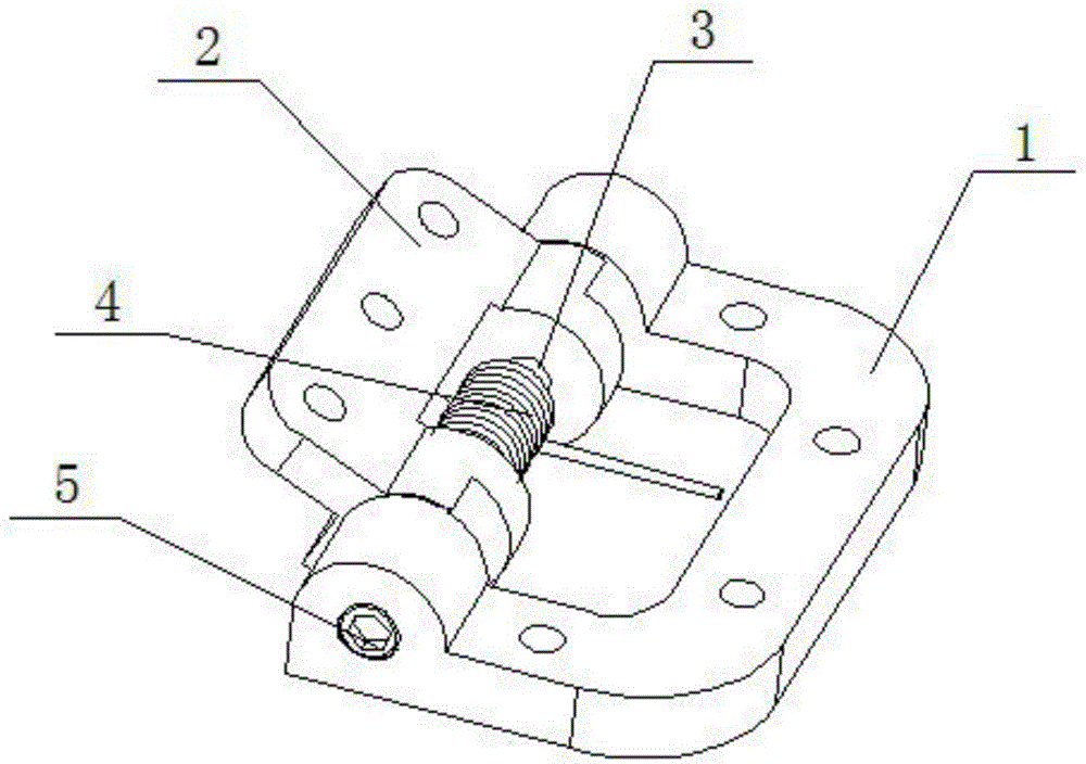
[0028] A hinge for deploying a cubic star solar cell array, comprising a body mounting plate fixing part 1, an unfolding array fixing part 2, a positioning shaft 3 and a torsion spring 4; 2 Matches the shape surrounded by the body mounting plate fixing part 1, the positioning shaft 3 is fixed between the body mounting plate fixing parts 1, and rotates with the deployment array fixing part 2, the axis of the positioning shaft 3 is the body mounting plate fixing part 1 and the center of rotation of the unfolding array fixing member 2 are mutually rotatable, on the opposite end faces between the body mounting plate fixing member 1 and the deploying array fixing member 2 are staggered and provided with limiting protrusions on the same rotating surface, and the body mounting plate fixing member The angle formed by 1 and the deployment array fixing part 2 is determined by the oblique angle of the mutual limit protrusions between the two, and...
PUM
 Abstract
Description
Claims
Application Information