Railway vehicle brake disc plate and combined warping prevention shaft-mounted brake disc

A technology for rail vehicles and brake discs, applied in the directions of brake discs, brake types, brake components, etc., it can solve the problems of axial warping deformation, disassembly obstacles, and eversion of joints, so as to improve the connection strength and strengthen The effect of integrity and high connection strength

Active Publication Date: 2015-12-02
南京北交轨道交通新材料科技有限公司 +1
View PDF6 Cites 10 Cited by
  • Summary
  • Abstract
  • Description
  • Claims
  • Application Information

AI Technical Summary

Problems solved by technology

After the disc body warps, it will lead to uneven pressure distribution of the brake pads, resulting in abnormal wear of the brake pads and aggravating the thermal damage of the disc surface, resulting in frequent replacement of the brake pads, increasing operating costs and reducing the service safety of the brake discs
[0004] In addition, when installing the brake disc, the brake disc is placed on the wheel shaft. When replacing the brake disc, the brake disc needs to be taken out along the axial direction of the wheel shaft. Since the wheel shaft is also equipped with other mechanisms or devices, these Mechanisms or devices are obstacles to dismantling the brake disc, and these mechanisms or devices have to be removed first when disassembling the brake disc, so the replacement of the existing brake disc is very complicated
[0005] People may think of opening and closing to solve this problem, but when the assembled brake disc rotates at high speed, the joints of the opening and closing discs will valgus and axially warp.

Method used


Image

  • Railway vehicle brake disc plate and combined warping prevention shaft-mounted brake disc
  • Railway vehicle brake disc plate and combined warping prevention shaft-mounted brake disc
  • Railway vehicle brake disc plate and combined warping prevention shaft-mounted brake disc

Examples


Embodiment 1

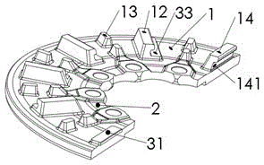
[0026] refer to figure 1 , a rail vehicle brake disc, comprising: a semi-annular disc 1, a flange 2 is connected to the inner ring of the semi-annular disc 1, and through holes are arranged on the flange 2 and the through holes are uniformly distributed in the circumferential direction, Wide cooling ribs 12 and narrow cooling ribs 13 are evenly distributed on the semi-annular disk 1 in the circumferential direction, quasi-wide cooling ribs 14 are provided at one end of the semi-annular disk 1, and a boss 31 is provided at the other end of the semi-annular disk 1. The boss 31 extends along the circumferential direction of the semi-annular disc 1 and forms a protruding part of the boss protruding from the other end of the semi-annular disc 1 , and a radial groove 141 which doubles as a circumferential connection is provided on the quasi-wide cooling rib 14 Moreover, the radial groove 141 also used for circumferential connection can accommodate the protruding portion of the boss ...

Embodiment 2

[0028] see Figure 5, a combined anti-warping shaft-mounted brake disc, including a disc hub 4 and two brake disc bodies respectively arranged on both sides of the disc hub 4 and fixed with the disc hub 4, the brake disc body consists of 2 The brake discs of rail vehicles are connected to each other. The fixing of the disc hub 4 and the brake disc body is a common fixing method in the prior art. Specifically, elastic pins 5 can be set on the hub 4 to realize the disc body The axial positioning of the disc hub 4 and the brake disc body are fixed by fasteners such as bolts;

[0029] refer to figure 1 , the rail vehicle brake disc comprises a semi-annular disc 1, a flange 2 is connected to the inner ring of the semi-annular disc 1, and a through hole is arranged on the flange 2 and the through holes are uniformly distributed in the circumferential direction, and in the semi-annular disc 1 The annular disk 1 is evenly distributed with wide cooling ribs 12 and narrow cooling ribs...

Embodiment 3

[0033] see Figure 5 , a combined anti-warping shaft-mounted brake disc, comprising a disc hub 4 and two brake disc bodies respectively arranged on both sides of the disc hub 4 and fixed to the disc hub 4, the brake disc body consists of 2 The rail vehicle brake discs are connected to each other;

[0034] refer to figure 1 , the rail vehicle brake disc comprises a semi-annular disc 1, a flange 2 is connected to the inner ring of the semi-annular disc 1, and a through hole is arranged on the flange 2 and the through holes are uniformly distributed in the circumferential direction, and in the semi-annular disc 1 The annular disk 1 is evenly distributed with wide cooling ribs 12 and narrow cooling ribs 13 in the circumferential direction. One end of the semi-annular disk 1 is provided with quasi-wide cooling ribs 14, and the other end of the semi-annular disk 1 is provided with a boss 31. The boss 31 extends along the circumferential direction of the semi-annular disk 1 and for...


PUM


Abstract

The invention provides a railway vehicle brake disc plate and a combined warping prevention shaft-mounted brake disc. The railway vehicle brake disc plate comprises a semi-annular disc, wherein a flange is connected to the inner ring of the semi-annular disc; through holes are formed in the flange and uniformly distributed in the circumferential direction; wide radiating ribs and narrow radiating ribs are uniformly distributed on the semi-annular disc in the circumferential direction; a quasi wide radiating rib is arranged at one end of the semi-annular disc, and a lug boss is arranged at the other end of the semi-annular disc; the lug boss extends in the circumferential direction of the semi-annular disc and forms a lug boss projection protruding out of the other end of the semi-annular disc; and a radial groove which can be also used for circumferential connection is formed in the quasi wide radiating rib and can accommodate the lug boss projection and the part, above the radial groove, of the quasi wide radiating rib. The combined warping prevention shaft-mounted brake disc comprises a disc hub and two brake disc bodies respectively arranged on two sides of the disc hub and fixed with the disc hub, wherein each brake disc body consists of two railway vehicle brake disc plates which are mutually connected.

Description

technical field [0001] The invention relates to the technical field of rail vehicle braking, in particular to a rail vehicle brake disc, a dynamic combined anti-warping shaft-mounted brake disc and an assembly method. Background technique [0002] When the train running speed is above 120km / h, the traditional brake shoe-wheel tread braking can no longer meet the requirements of train braking. Disc brakes. [0003] The brake disc is a key component that converts the kinetic energy of the train into heat energy through the disc energy. The brake discs developed at home and abroad include: cast iron discs, forged steel discs, cast steel discs, aluminum matrix composite discs, C / C composite disc body. The steel disc has the characteristics of high technical maturity, low cost and wide range of applicable speeds. It has been widely used in fast and high-speed EMU trains in developed countries abroad. Brake discs have complex service conditions and are subject to coupling effec...

Claims


Application Information

Patent Timeline
Patent Type & Authority Applications(China)
IPC IPC(8): F16D65/12F16D65/84
Inventor 曾奇夫
Owner 南京北交轨道交通新材料科技有限公司
Why Eureka
Try Eureka