Mechanical seal with controllable bevel seal face seal ring

A technology of mechanical sealing device and sealing end, which is applied in the direction of mechanical equipment, engine sealing, engine components, etc. It can solve the problems of difficult surface taper, inability to adjust, and change in the size of the tapered cone angle of the sealing end surface, so as to achieve high rigidity and load bearing ability, reduce cost and difficulty, reduce the effect of surface deformation

Active Publication Date: 2017-04-26
永嘉县环球机械密封件厂
View PDF4 Cites 0 Cited by
  • Summary
  • Abstract
  • Description
  • Claims
  • Application Information

AI Technical Summary

Problems solved by technology

Considering that when the medium flows through the end face, sufficient hydrodynamic pressure effect can be formed to obtain greater opening force and rigidity of the fluid film. The surface quality (mainly referring to surface roughness, waviness, and shape) of the sealing end face of the shaped surface is very high, which makes it difficult to obtain a high-precision tapered surface with general processing techniques and equipment
On the other hand, in the case that the machining accuracy can be effectively guaranteed, the taper angle of the sealing end face may change due to factors such as detection means, assembly accuracy, and the influence of medium pressure and temperature during work.
This makes it difficult for the conical surface of the conical surface mechanical seal to be consistent with the designed conical shape during actual work, thus affecting the stability of the sealing work
[0005] Therefore, for mechanical seals with conical end faces, when the taper angle of the end face is very small and the surface quality requirements are very high, any link during processing, testing, assembly and operation may affect the conical cone angle. The size and shape have a significant effect, resulting in insufficient end-face hydrodynamic effect, and it is difficult to obtain sufficient end-face fluid film opening force and stiffness, so that the seal cannot work properly
[0006] To sum up, as an effective non-contact mechanical seal device, the conical surface mechanical seal has two significant problems: one is that the processing of the conical surface is difficult and the process requirements are very high; the other is that the actual work is difficult. Surface taper is difficult to keep up with design taper and cannot be adjusted

Method used


Image

  • Mechanical seal with controllable bevel seal face seal ring
  • Mechanical seal with controllable bevel seal face seal ring
  • Mechanical seal with controllable bevel seal face seal ring

Examples


Embodiment Construction

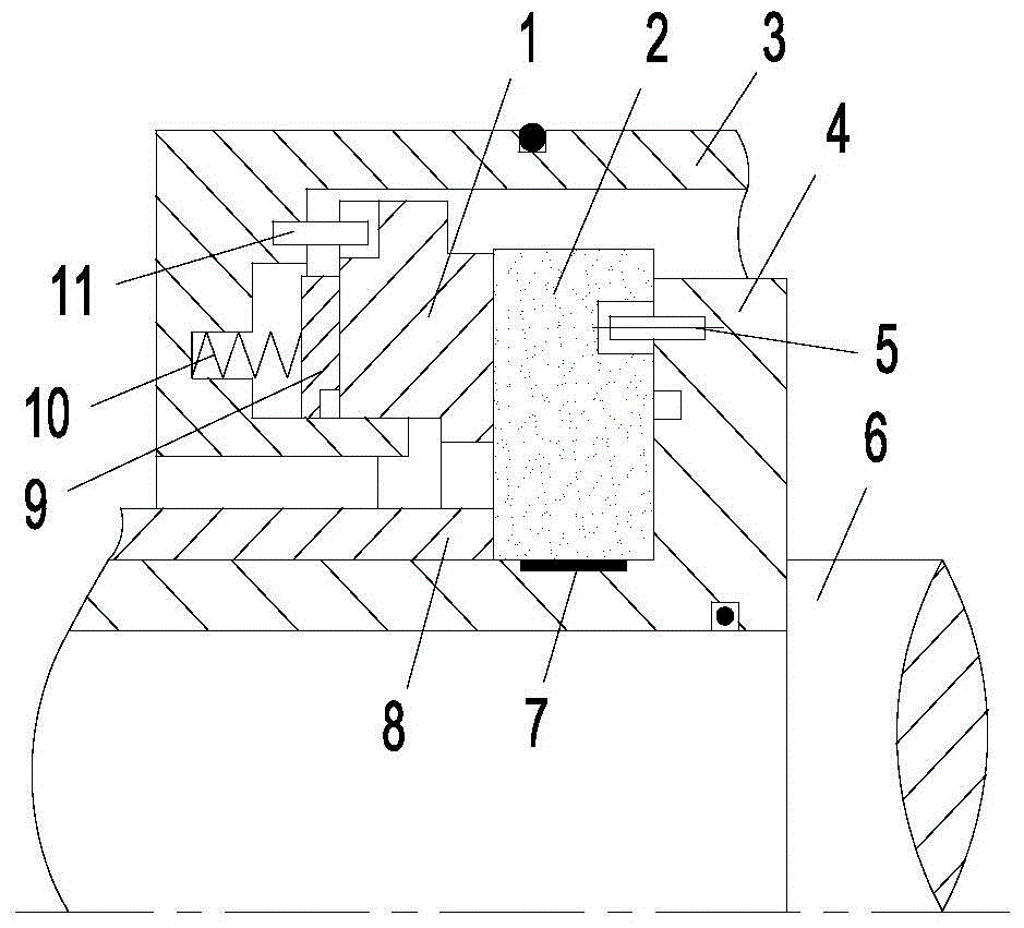
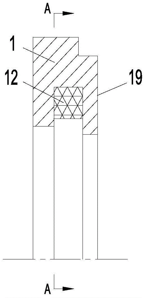
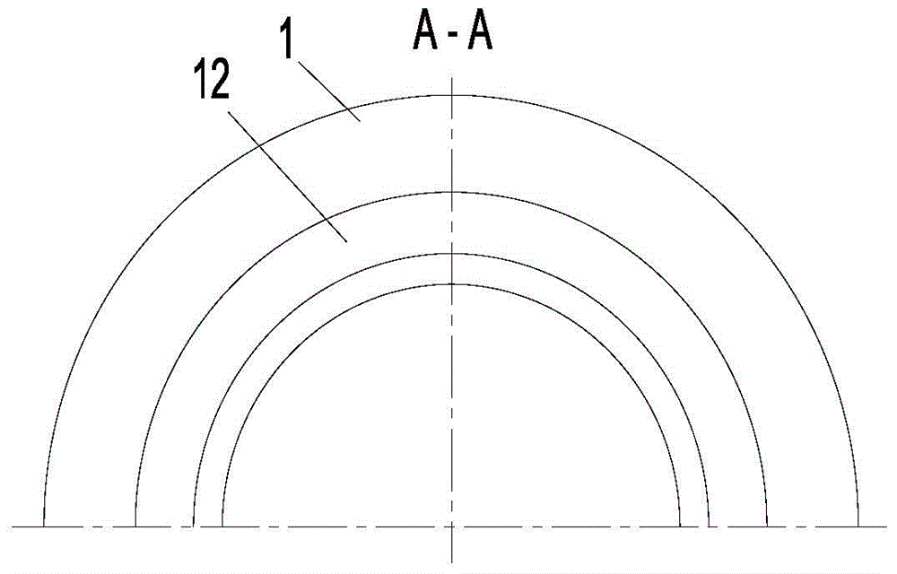
[0022] Such as figure 1Shown is the basic structural form of the mechanical seal device commonly used at present, with a static ring 1, a moving ring 2, a static ring seat 3, a shaft sleeve 4, a transmission pin 5, a tolerance ring 7, a compression sleeve 8, a push ring 9. The spring 10 and the anti-rotation pin 11 are components. The static ring 1 and the moving ring 2 are arranged coaxially opposite each other, and their opposite end surfaces are sealing surfaces. Static ring 1 is radially vacantly sleeved on static ring seat 3, axially supported by push ring 9 and spring 10, and circumferentially positioned by anti-rotation pin 11, so that static ring 1 can only freely float axially. The moving ring 2 is radially expanded by the tolerance ring 7 on the outer cylindrical surface of the shaft sleeve 4, axially contacts with the stepped surface of the shaft sleeve 4 and is compressed axially by the compression sleeve 8, and is circumferentially connected by the transmission p...


PUM


Abstract

The invention relates to a mechanical seal device with seal rings with controllable cone bevel seal end faces. The mechanical seal device is provided with a moving ring capable of synchronously rotating along with a rotary shaft and a non-rotating static ring connected with a static ring seat. Axially-opposite end faces between the moving ring and the static ring serve as respective seal faces. The seal face of at least one of the static ring and the moving ring is of a plane structure, and an annular electric heating structure concentric with the static ring and / or the moving ring is arranged at the position, spaced from the seal face, in the static ring and / or the moving ring and connected with a control system. On the basis of an existing end face processing technology, the seal faces can be processed into planes, the cone bevel structure seal faces with high surface quality and controllable cone angle sizes can be obtained on the planes through heating control over the annular electric heating structures, and therefore the influences of various factors on the seal effect can be effectively eliminated, a very good fluid hydrodynamic effect can be generated, and very ideal fluid film opening force and rigidity are obtained.

Description

technical field [0001] The invention relates to an end face sealing device, in particular to a mechanical sealing device with a controllable cone-slope sealing end face sealing ring. Background technique [0002] Mechanical sealing devices and technologies have been widely used in the axial end face seals of many rotating machines, such as the shaft end seals of various types of pumps, compressors, expanders, separators, reactors and other rotating machines. Such as figure 1 As shown, the basic structure of the fluid end face non-contact mechanical seal device that has been reported and / or used at present usually includes a stationary ring (static ring) 1, a rotating ring (moving ring) 2, a static ring seat 3, a shaft Cover 4, drive pin 5, tolerance ring 7, compression sleeve 8, push ring 9, spring 10, anti-rotation pin 11 etc. constitute components. The static ring 1 and the moving ring 2 are arranged coaxially opposite each other, and their opposite end surfaces are seal...

Claims


Application Information

Patent Timeline
Patent Type & Authority Patents(China)
IPC IPC(8): F16J15/16
Inventor 王和顺朱维兵
Owner 永嘉县环球机械密封件厂
Why Eureka
Try Eureka