Double-mode leak detector and detection method

A detection method and technology of a leak detector are applied in the direction of measuring the acceleration and deceleration rate of the fluid, using the liquid/vacuum degree for liquid tightness measurement, etc., which can solve the problems of increasing the running time, affecting the detection efficiency, and increasing the purchase cost, etc. Achieve the effect of prolonging service life, high detection efficiency and improving accuracy

Inactive Publication Date: 2015-12-02
BOYI TIANJIN PNEUMATIC TECH INST
View PDF14 Cites 2 Cited by
  • Summary
  • Abstract
  • Description
  • Claims
  • Application Information

AI Technical Summary

Problems solved by technology

[0003] The existing air-tight leak detectors mainly have the following disadvantages: strong equipment limitations: it is impossible to detect workpieces with more than two leakage states (such as air tightness when the valve is closed and air flow when the valve is opened) through a single device; High purchase cost: when it is necessary to test the flow characteristics and air tightness, it is necessary to purchase equipment separately, which increases the purchase cost; low detection efficiency: because the flow and air tightness detection needs to be completed by two leak detectors, additional running time is added , which affects the detection efficiency; workpieces with excessive leakage will damage the life of the differential pressure sensor: workpieces with small leakage cannot be verified by flow-type air-tight leak detectors, and only differential-pressure air-tight leak detectors can be used instrument
However, for workpieces with large leakage, if the leakage size cannot be known in advance, using a differential pressure air-tight leak detector will cause the differential pressure sensor to exceed the range, and long-term multiple detections will damage the differential pressure sensor. life, and the workpiece with excessive leakage cannot detect accurate leakage when using a differential pressure airtight leak detector.

Method used


Image

  • Double-mode leak detector and detection method

Examples


Embodiment Construction

[0028] It should be noted that the embodiments of the present invention and the features in the embodiments can be combined with each other if there is no conflict.

[0029] Hereinafter, the present invention will be described in detail with reference to the drawings and in conjunction with the embodiments.

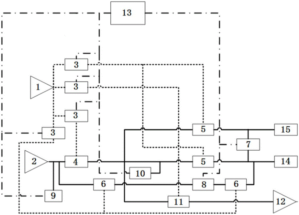
[0030] The dual-mode leak detector of the present invention, such as figure 1 As shown, it includes the detection gas source 2, the inflation valve 4, the reference gas path and the tested gas path. The detection gas source 2 is connected to the inflation valve 4, and the reference gas path and the tested gas path are respectively connected after the inflation valve 4. A balance valve 5 is connected to the gas path and the tested gas path, and a differential pressure sensor 7 is connected in series between the gas path behind the reference gas path balance valve 5 and the gas path behind the tested gas path balance valve 5;

[0031] The dual-mode leak detector also includes a f...


PUM


Abstract

The invention provides a double-mode leak detector and a detection method. The double-mode leak detector comprises a detection gas source, a gas charging valve, a reference gas channel and a gas channel to be detected. The detection gas source is connected with the gas charging valve and is connected with the reference gas channel and the gas channel to be detected behind the gas charging valve. The reference gas channel and the gas channel to be detected are connected with balance valves respectively. a pressure difference sensor is in series connection between gas channels behind the reference gas channel and the balance valve of the gas channel to be detected. The double-mode leak detector also comprises a flow detection gas channel. The flow detection gas channel is connected with two flow detection values and a flow sensor. The flow sensor is located between the two flow detection valves. The double-mode leak detector and the detection method has advantages of wide application scope, low purchase cost, small land occupation space, high detection efficiency and the like. In addition, the balance valves in the reference gas channel and the gas channel to be detected can protect the pressure difference sensor and prolong the service life of the pressure difference sensor. The flow detection valve in the flow detection gas channel can ensure accuracy of the detection result during detection in a pressure difference mode.

Description

Technical field [0001] The invention belongs to the technical field of airtight detection, and specifically relates to a dual-mode leak detector, and also relates to a detection method of the dual-mode leak detector. Background technique [0002] The current air-tight leak detectors mainly include the following two types: Flow-type air-tight leak detectors used for the detection of large-leakage workpieces (flow characteristics): the gas source inflates the measured object through the flow sensor, and the flow sensor detects the Measure the gas flow of the object, and then obtain the leakage value (flow value) of the workpiece; the differential pressure airtight leak detector for the detection of small leakage workpieces: the gas source is first to the measured object and the reference object (the reference object is Known good products without leakage) inflate, and then stop the inflation during the detection process, so that the reference object and the measured object form a c...

Claims


Application Information

Patent Timeline
Patent Type & Authority Applications(China)
IPC IPC(8): G01M3/26
Inventor 马诏韡刘德亮
Owner BOYI TIANJIN PNEUMATIC TECH INST
Why Eureka
Try Eureka