Fracture-cavity reservoir inter-well communication passage and flow parameter characterization method

A technology for connecting channels and flow parameters, applied in the direction of electrical digital data processing, special data processing applications, instruments, etc., can solve the problems of unfeasible operation, increasing the complexity of karst channel parameters, etc.

Inactive Publication Date: 2015-12-02
SOUTHWEST PETROLEUM UNIV
View PDF3 Cites 23 Cited by
  • Summary
  • Abstract
  • Description
  • Claims
  • Application Information

AI Technical Summary

Problems solved by technology

The division of connectivity types is necessary for theoretically understanding the morphology of karst systems, bu...

Method used


Image

  • Fracture-cavity reservoir inter-well communication passage and flow parameter characterization method
  • Fracture-cavity reservoir inter-well communication passage and flow parameter characterization method
  • Fracture-cavity reservoir inter-well communication passage and flow parameter characterization method

Examples


Embodiment 1

[0177] Example 1: TK221 well group.

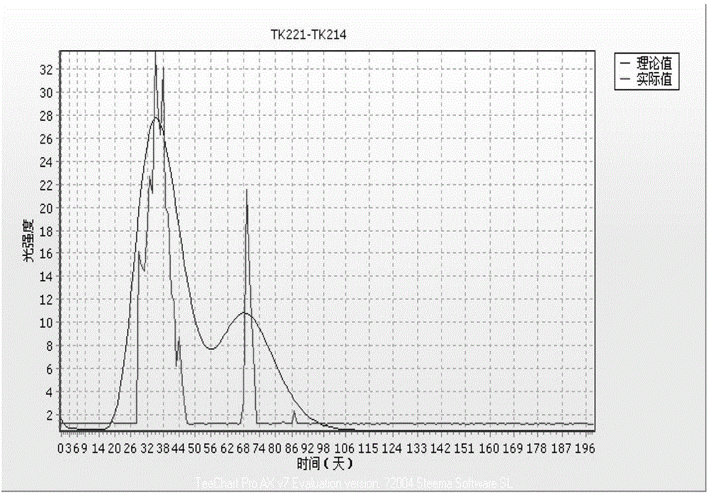
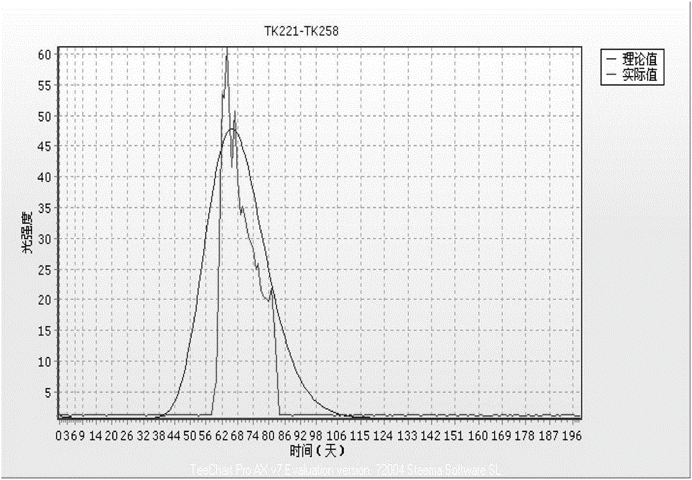
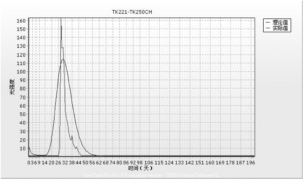
[0178] The injection well is TK221, corresponding to 4 tracer production wells TK214, TK258, TK250CH, TK251CH during the monitoring period. From the tracer curves, well TK214 detected two independent peaks, indicating that there were two independent communication channels between wells TK221 and TK214, and the tracer curves monitored by the other three wells were all single-peak curves, indicating that each injection The communication channel between production wells is a single channel, such as figure 1 , 2 , 3,4 shown in the measured curve. The basic data used for fitting are shown in Table 1 (the data of each point on the measured trace curve are omitted)

[0179] Table 1 Basic parameters of tracer curve fitting of well group TK221

[0180]

[0181] The well group fitting results are shown in Table 2 and figure 1 , 2 , 3,4 in the theoretical curve.

[0182] Table 2 Calculation results of connection parameters of TK221 well gro...

Embodiment 2

[0186] Embodiment 2: TK634 well group.

[0187] The injection well is TK634, corresponding to 7 tracer production wells TK747, TK744, TK711, TK625, T7-607, S80, and TK667 during the monitoring period. The well area is an area where weathering crust is developed. From the measured trace curves, the trace curves of each well are composed of several random small wave peaks, reflecting that the flow space between injection and production wells is actually formed by many small connecting channels. Parallel channel structures such as Figures 5 to 11 The shape of the measured curve is shown in the middle.

[0188] The measured curve can be approximated as having several main peaks according to the needs of interpretation. Well TK214 detected two independent peaks, indicating that there were two independent communication channels between wells TK221 and TK214, and the tracer curves monitored by the other three wells were all single-peak curves, indicating that the communication cha...


PUM


Abstract

The present invention relates to the technical field of reservoir description in oil field development, in particular to a fracture-cavity inter-well communication passage and flow parameter characterization method. The method comprises the following steps of: (A) establishing an analytical expression of describing a fracture-cavity reservoir inter-well flow rule; (B) establishing a tracing production concentration curve fitting mathematical model; (C) performing curve fitting model solution; and according to principles of the three steps, compiling fracture-cavity reservoir tracing curve fitting software, performing fitting on a theoretical tracing curve and an actually measured tracing curve by a method of adjusting a parameter on a software interface, and simultaneously carrying out calculation to obtain mass mik, a flow velocity vik, an orifice area Aik and a flow duct length lik of a fracture-cavity injection tracer so as to implement characterization on a communication passage and a flow parameter. According to the present invention, an established model of describing the flow rule of the fracture-cavity reservoir tracer further accords with the true situations; quantitative calculation characterization on the fracture-cavity reservoir inter-well communication passage and the flow parameter is implemented; and in the fitting process, automatic fitting of a computer and parameter regulation of a worker are combined.

Description

technical field [0001] The invention relates to the technical field of oil reservoir description in oilfield development, in particular to a characterization method for inter-well communication channels and flow parameters of fracture-cavity oil reservoirs. Background technique [0002] At present, the research methods of interwell connectivity at home and abroad mainly include wireline logging, formation correlation, geochemistry, well testing, correlation analysis of injection-production well production dynamics, and tracer testing, among which the first three methods belong to static evaluation methods. For reservoir developers, more attention is paid to the dynamic connectivity between wells during reservoir development. The study of reservoir connectivity, especially the dynamic connectivity between injection and production wells, is the basic work content for comprehensively understanding the geological characteristics of reservoirs and improving reservoir recovery. ...

Claims


Application Information

Patent Timeline
IPC IPC(8): G06F17/50
Inventor 李科星金发扬蒲万芬荣元帅
Owner SOUTHWEST PETROLEUM UNIV
Why Eureka
Try Eureka