Low-voltage welding transformer and operation method thereof

A technology for welding transformers and operation methods, applied in the field of transformers, can solve the problems of long operation time, not easy to control, easy to fuse wires, etc., and achieves the effects of good heat dissipation and strong short-circuit resistance.

Inactive Publication Date: 2015-12-02
CHANGZHOU INST OF MECHATRONIC TECH
View PDF6 Cites 5 Cited by
  • Summary
  • Abstract
  • Description
  • Claims
  • Application Information

AI Technical Summary

Problems solved by technology

Now most factories use gas welding to connect wires. During gas welding, thin wires are easy to fuse, but it takes a long time for thick copper flat wires to melt. It is not easy to control, and the operation time is relatively long, which wastes man-hours.

Method used


Image

  • Low-voltage welding transformer and operation method thereof
  • Low-voltage welding transformer and operation method thereof
  • Low-voltage welding transformer and operation method thereof

Examples


Embodiment 1

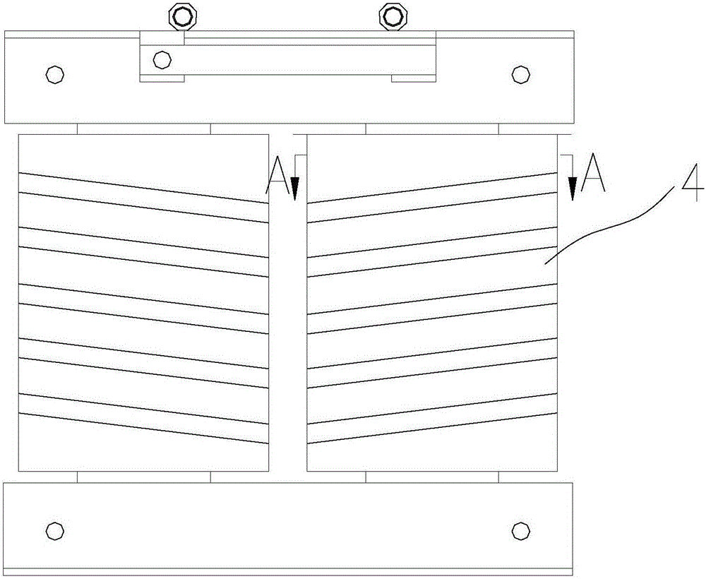
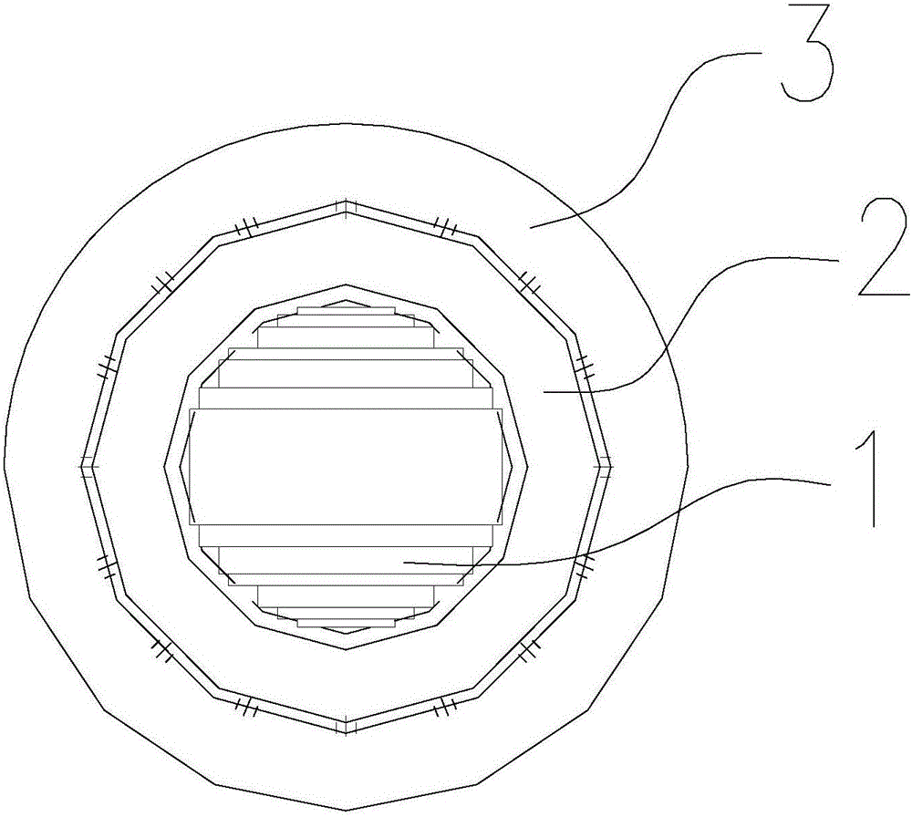
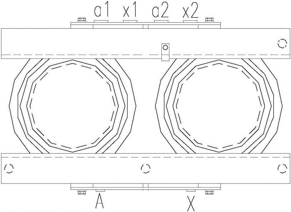
[0025] Such as Figure 1 to Figure 4 As shown, the present invention provides a low-voltage welding transformer, including: two sets of transformer winding assemblies with the same structure, the transformer winding assembly includes: an iron core 1, and the iron core 1 is provided with a primary winding 2 and a secondary Winding 3; the primary winding 2 in the two sets of transformer winding assemblies is connected in series (the two input ends of the secondary winding 2 are A and X respectively, which are suitable for accessing single-phase 380V AC voltage), and are respectively connected to the corresponding secondary windings in the transformer windings. The windings 3 are coupled; the two secondary windings 3 respectively lead out two output ends; and the two output ends respectively led out of the two secondary windings 3 are connected correspondingly to form a series output or a parallel output of the two secondary windings 3 .

[0026] The iron core 1 is located in the...

Embodiment 2

[0036] Such as Figure 1 to Figure 4 As shown, on the basis of Embodiment 1, the present invention also provides a method for operating a low-voltage welding transformer.

[0037] Wherein, the low-voltage welding transformer includes: two sets of transformer winding assemblies with the same structure, and the transformer winding assemblies include: an iron core 1, and the iron core 1 is provided with a primary winding 2 and a secondary winding 3; two sets of transformer winding assemblies The primary windings 2 in the winding assembly are connected in series, and are respectively coupled with the corresponding secondary windings 3 in the transformer winding; the two secondary windings 3 respectively lead to two output terminals; the operation method includes: leading the two secondary windings 3 respectively to The two output ends of the two outputs are connected correspondingly to form a series output or a parallel output of the secondary winding 3 .

[0038] Moreover, it is...


PUM


Abstract

The invention relates to a low-voltage welding transformer and an operation method thereof. The low-voltage welding transformer comprises two groups of transformer winding components which are the same in structure, and each transformer winding component comprises an iron core, a primary winding and a secondary winding, wherein each primary winding and the corresponding secondary winding are arranged outside the corresponding iron core; primary windings in the two groups of transformer winding components are in series connection, and each primary winding is coupled with the corresponding secondary winding in the transformer windings; two circuits of output ends are led out of two secondary windings; the two circuits of output ends led out of the two secondary windings respectively are connected correspondingly, so that the series connection output or parallel connection output of the two secondary windings is formed.

Description

technical field [0001] The invention relates to a transformer, in particular to a low-voltage welding transformer and an operating method thereof. Background technique [0002] At present, the production process of the domestic transformer or motor industry is roughly the same. In the process of winding the coil, since the weight of the wire on the reel is certain, and winding a coil often requires several coils of wire, it is necessary to wind the coil. Connect wires from different reels. Now most factories use gas welding to connect wires. During gas welding, thinner wires are easy to fuse, but it takes a long time for thick copper flat wires to melt. A welding transformer capable of outputting stable current is needed to improve welding quality and shorten working hours. Contents of the invention [0003] The object of the present invention is to provide a low-voltage welding transformer and its operation method. The output terminals of the secondary windings are draw...

Claims


Application Information

Patent Timeline
Patent Type & Authority Applications(China)
IPC IPC(8): H01F27/28H01F41/04
Inventor 张平泽张雨迪王浩宇徐雪荣唐帅帅
Owner CHANGZHOU INST OF MECHATRONIC TECH
Why Eureka
Try Eureka