
Spiral plate-type winding

A spiral plate type and spiral type technology, applied in the direction of transformer/inductor coil/winding/connection, electrical components, transformer/inductor parts, etc., can solve the problems of area reduction, poor manufacturing process, etc., and improve the filling factor , strong short-circuit resistance and strong overload capacity

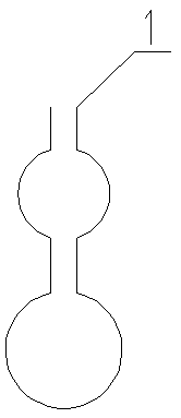
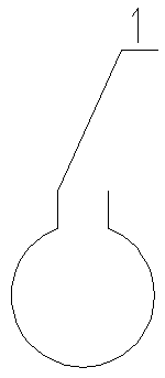
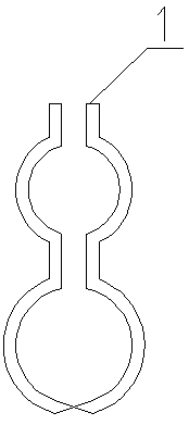
Pending Publication Date: 2019-07-26
孙崇山
View PDF0 Cites 0 Cited by
  • Summary
  • Abstract
  • Description
  • Claims
  • Application Information

AI Technical Summary

Problems solved by technology

When it is used in shell-type transformers, because it is wound with bare wires, the manufacturing process is poor. Since multiple wires are superimposed and wound in parallel, each wire needs to be chamfered, so the area will be reduced.

Method used


Image

  • Spiral plate-type winding
  • Spiral plate-type winding
  • Spiral plate-type winding

Examples


example 1

[0040] Example 1. For the low-voltage winding of S13—400 / 10±2×0.25% / 0.4, select spiral plate winding without end insulation, such as Figure 7 .

[0041] Because of the six magnetic balance groups, there are six sets of windings.

[0042] Low-voltage winding: spiral plate winding with a flattened structure, with an oblong cross section.

[0043] The number of turns is 24 turns.

[0044] Copper plate 5×41.

[0045] Two single magnetic balance groups with 4 turns.

[0046] Two double magnetic balance groups with 8 turns.

[0047] The inner diameter of the short shaft is 165mm.

[0048] The outer diameter of the short shaft is 247mm.

[0049] The inner diameter of the major axis = the inner diameter of the minor axis + the distance between the straight lines = 165 + 40 × 2 = 245 mm.

[0050] Long shaft outer diameter = short shaft outer diameter + straight line distance = 241 + 40 × 2 = 321mm.

[0051] Winding height = 27 mm.

[0052] Winding height=27mm for impedance voltage calculation.


PUM


Abstract

The invention relates to a winding for a transformer. The winding is mainly applied to a centrifugal transformer arranged in a shell type and winding staggered type. Compared with a spiral winding, the spiral plate-type winding has the advantages of high mechanical strength, high short-circuit resistant capability, good cooling effect, high overload capability and compact structure, the filling coefficient in an iron core window is improved, and a lead is convenient to install.

Description

Technical field [0001] The invention is a winding for a transformer. Mainly used in core type transformers with shell type and winding staggered arrangement. Background technique [0002] Transformer is one of the most important power equipment used in power grids and power systems, mainly composed of iron core and windings (also called coils). Transformer windings mainly include cylindrical, spiral, continuous, tangled, plug-in capacitive (inner shielded), tangled continuous, double-cake, and eight-shaped coils. [0003] There is also a special winding type in the transformer. When the number of turns of the low-voltage winding of the electric furnace and rectifier transformer is less than 3 turns, the winding made of copper plate can be used, such as figure 1 , 2 , 3, 4. [0004] The spiral winding is a structure of the transformer winding. Each turn is composed of multiple wires (flat wires, similar in shape to a rectangle, divided into width and thickness) in parallel, and each...

Claims


Application Information

Patent Timeline
Patent Type & Authority Applications(China)
IPC IPC(8): H01F27/28
CPCH01F27/2847H01F2027/2857
Inventor 高大为孙铭鸿孙崇山
Owner 孙崇山
Learn More