Distribution transformer with staggered windings

A distribution transformer, interlaced technology, applied in the field of distribution transformers, can solve the problem of low pass rate of sudden short-circuit test

Active Publication Date: 2019-06-04
孙崇山
View PDF10 Cites 1 Cited by
  • Summary
  • Abstract
  • Description
  • Claims
  • Application Information

AI Technical Summary

Problems solved by technology

Due to cost reasons, some domestic production and scientific research institutes have designed a batch of distribution transformers with core-ty

Method used


Image

  • Distribution transformer with staggered windings
  • Distribution transformer with staggered windings
  • Distribution transformer with staggered windings

Examples


example 1

[0066] Example 1, S13—400 / 10±2×0.25% / 0.4

[0067] National standard: load loss Pk=4200W

[0068] No-load loss P0=410W

[0069] No-load current percentage I0%=0.8%

[0070] Impedance voltage percentage Uk%=4%

[0071] Total loss P=4930 W

[0072] 1. New transformer S13—400 / 10±2×0.25% / 0.4

[0073] Design scheme: the cross section of the core winding is oblong

[0074] The core length and short axis ratio is 1:1.49, the small circle diameter of the core is Φ155mm, the main stage of the core is thickened by 33mm, and the cross-sectional area of ​​the core is 280.006cm 2 . Core flux density Bm=1.546T, M0=255mm, Hw=400mm.

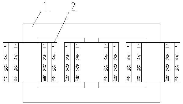
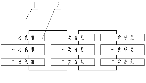
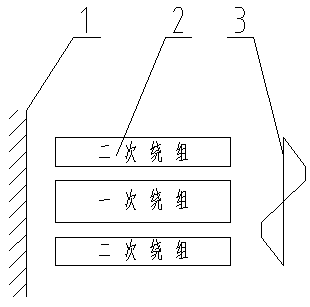
[0075] Winding structure: staggered, six magnetic balance groups.

[0076] High-voltage winding: It is a disc winding with a flattened structure, and the number of turns is 630 turns, 600 turns, and 570 turns. Wire gauge ZB—0.32.12×4. Each double magnetic balance group has 15 turns / layer, a total of 15 layers.

[0077] Low-voltage winding: spiral plate...


PUM


Abstract

The invention relates to a novel distribution transformer, which combines the structural advantages of the existing shell-type transformers and core-type transformers and can completely replace the existing distribution transformers. The cost is greatly reduced, and the passing rate of burst short circuit test is basically 100%. The windings of the transformer have a good cooling effect and strongoverload capability. The transformer has large limit capacity and is convenient to transport. The advantage in ultimate capacity is superior to that of the shell-type transformer. When vertical transportation is inconvenient, the transformer can be inverted for transformation to reduce the height of transportation. The transformer has the advantages of compact structure, small size, low overall weight, compact structure, easy lead installation, uniform capacitance distribution, reliable insulation, and strong lightning resistance and switching overvoltage capability.

Description

technical field [0001] The invention is a novel distribution transformer, which is used to replace the existing distribution transformer with concentric arrangement of windings. Background technique [0002] Distribution transformer is an important power equipment used in power grid and power system, mainly composed of iron core and winding (also called coil). Distribution transformers are mainly core-type transformers with concentric windings. [0003] The basic structure of a distribution transformer is as follows: figure 1 As shown (three-phase), the cross-section of the core column is circular, the placement method is vertical, the cross-section of the coil is also circular, the high-voltage and low-voltage coils are concentrically sleeved on the core column in turn, the coil surrounds the core, and the coils are concentrically arranged. The cross-section of the core column is made of multi-level core sheets with different widths and thicknesses. The circumscribed shap...

Claims


Application Information

Patent Timeline
IPC IPC(8): H01F27/28H01F27/245H01F27/12H01F30/12
Inventor 高大为孙铭鸿孙崇山
Owner 孙崇山
Why Eureka
Try Eureka