Magnetic blow-out switch protective device

A technology of a demagnetization switch and a protection device, which is used in the control of generators, electrical components, control systems, etc., can solve the problems of arcing and burning of the demagnetization switch contacts, increasing operating costs, and reducing the reliability of the demagnetizing switch. It is not easy to be damaged and ensures the effect of rapid demagnetization

Inactive Publication Date: 2015-12-02
DFEM CONTROL EQUIPMENT CO LTD +1
View PDF5 Cites 5 Cited by
  • Summary
  • Abstract
  • Description
  • Claims
  • Application Information

AI Technical Summary

Problems solved by technology

However, in this process, the de-excitation switch is subjected to high voltage and current due to the effect of the reverse voltage of the inductance, so each time it trips, the contacts of the de-excitation switch will be arced and burned, and the de-excitation switch will be damaged after multiple trips. Generally, the main contact of the de-excitation switch needs to be replaced every 2-3 years, which increases the operating cost and reduces the reliability of the de-excitation switch.

Method used


Image

  • Magnetic blow-out switch protective device
  • Magnetic blow-out switch protective device
  • Magnetic blow-out switch protective device

Examples


no. 1 example

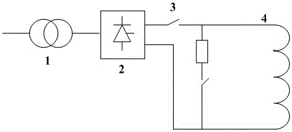
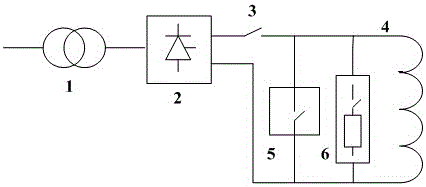
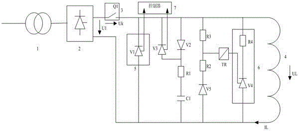
[0035] see figure 2 , The existing excitation system includes excitation transformer, 1, thyristor rectifier bridge 2, de-excitation switch 3 and load 4. The three-phase AC output terminal of the excitation transformer 1 is connected to the three-phase AC input terminal of the thyristor rectifier bridge 2, the first DC output terminal of the thyristor rectifier bridge 2 is connected to one end of the de-excitation switch 3, and the other end of the de-excitation switch 3 is connected to the One end of the load 4 is connected, and the other end of the load 4 is connected to the second DC output end of the thyristor rectifier bridge 2 .

[0036] It further includes a commutation branch 5 and a demagnetization branch 6 .

[0037] One end of the commutation branch 5 is connected to the other end of the de-excitation switch 3, and the other end of the commutation branch 5 is connected to the second DC output end of the thyristor rectifier bridge 2; the de-excitation branch 6 is c...

no. 2 example

[0041] see figure 2 , this embodiment also includes a commutation branch turn-on and turn-off control circuit and a demagnetization branch turn-on control circuit.

[0042] The on-off control circuit of the commutation branch is used to control the commutation branch to be turned on before the de-excitation switch is turned off and to be turned off after a certain period of time.

[0043] The conduction control circuit of the de-excitation branch is used to control the conduction of the de-excitation branch after the commutation branch is turned off.

[0044] Wherein, the commutation branch includes a thyristor V1; the on-off control circuit of the commutation branch includes a controller 7, a thyristor V3, a diode V2, a resistor R1 and a capacitor C1.

[0045] The cathode of the thyristor V1 is connected to the other end of the demagnetization switch 3 , and the anode of the thyristor V1 is connected to the DC terminal of the thyristor rectifier bridge 2 .

[0046] The ano...


PUM


Abstract

The invention discloses a magnetic blow-out switch protective device, and relates to the excitation control field of synchronous motors. The technical main points are that the magnetic blow-out switch protective device comprises a commutation branch and a magnetic blow-out branch, a three-phase AC power output end of an excitation transformer is connected to a three-phase AC power input end of a thyristor rectifier bridge, a first DC output end of the thyristor rectifier bridge is connected to one end of a magnetic blow-out switch, the other end of the magnetic blow-out switch is connected to one end of a load, the other end of the load is connected to a second DC output end of the thyristor rectifier bridge, one end of the commutation branch is connected to the other end of the magnetic blow-out switch, the other end of the commutation branch is connected to the second DC output end of the thyristor rectifier bridge, one end of the magnetic blow-out branch is connected to the other end of the magnetic blow-out switch, and the other end of the magnetic blow-out branch is connected to the second DC output end of the thyristor rectifier bridge, the commutation branch is used for conduction before the magnetic blow-out switch is turned off and then is cut off after keeping conducting for a period of time, and the magnetic blow-out branch is used for conduction after the commutation branch is cut off.

Description

technical field [0001] The invention relates to the field of excitation control of synchronous motors, in particular to a protection device for a de-excitation switch. Background technique [0002] In the synchronous generator excitation system, the main function of the excitation system is to convert the AC current into a controlled DC current. The conversion method generally uses a thyristor rectifier bridge. The input of the rectifier bridge is a three-phase AC power supply voltage, and the output is a pulsating DC voltage. It is connected to the load through the de-excitation switch, that is, the generator rotor circuit. [0003] The main function of the de-excitation switch is to connect the generator rotor to the rectified DC power supply. But the more important function is to effectively and quickly cut off the excitation power supply of the rotor winding when an accident occurs in the generator body or the power grid or other devices. [0004] The de-excitation swi...

Claims


Application Information

Patent Timeline
Patent Type & Authority Applications(China)
IPC IPC(8): H02P9/12
Inventor 汪大卫李宇俊王金荣
Owner DFEM CONTROL EQUIPMENT CO LTD
Why Eureka
Try Eureka