Polarizing plate and liquid crystal display device including the polarizing plate

A liquid crystal display device, polarizing plate technology, applied in optics, optical elements, polarizing elements, etc., can solve the problems of image quality deterioration and manufacturing cost increase, and achieve the effect of ensuring viewing angle, good price competitiveness, and maintaining image quality.

Active Publication Date: 2017-09-22
DONGWOO FINE CHEM CO LTD
View PDF6 Cites 0 Cited by
  • Summary
  • Abstract
  • Description
  • Claims
  • Application Information

AI Technical Summary

Problems solved by technology

However, in this case, there are also problems of image quality degradation and increased manufacturing costs.

Method used


Image

  • Polarizing plate and liquid crystal display device including the polarizing plate
  • Polarizing plate and liquid crystal display device including the polarizing plate
  • Polarizing plate and liquid crystal display device including the polarizing plate

Examples


Embodiment 1

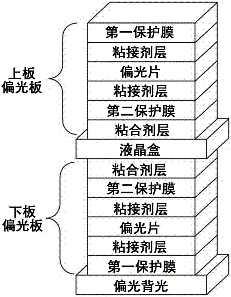
[0108] The actual measurement data of each optical film, liquid crystal cell and backlight of the present invention are as follows: figure 2 The structure shown is laminated on TECHWIZ LCD. On TECH WIZ LCD, the liquid crystal cell of the 55-inch PS-VA mode liquid crystal display device is parameterized and laminated.

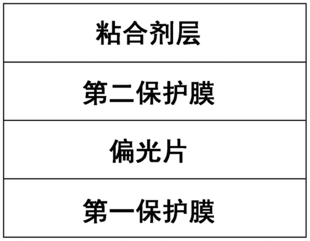
[0109] The liquid crystal display device is composed of a polarized backlight, a PS-VA mode liquid crystal cell of a lower polarizing plate and an upper polarizing plate. The upper polarizing plate and the lower polarizing plate respectively have an adhesive layer, a second protective film, an adhesive layer, a polarizer, an adhesive layer, and a first protective film laminated in order from the liquid crystal cell side.

[0110] The polarizer is added by stretching and dyeing PVA. The absorption axis of the backlight side polarizer is stacked in the vertical direction when viewed from the viewing side, while the absorption axis of the viewing side polarizer i...

Embodiment 2

[0126] Example 2: VA mode

[0127] Although carried out in the same manner as in Example 1, each of the first protective films of the upper plate and the lower plate is uniaxially stretched in the MD direction, and laminated with a front retardation value (RO) of 250 nm under a light source of 589 nm and Modified polystyrene film (PS) with a refractive index ratio (NZ) of 0.

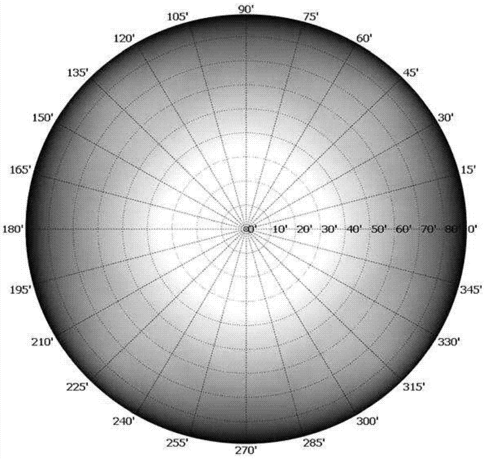
[0128] Figure 4 As a result of applying a voltage to the liquid crystal cell of the liquid crystal display device and counting rainbow spots from various directions, it was confirmed that no rainbow spots occurred at all.

Embodiment 3

[0129] Example 3: VA mode

[0130] Although carried out in the same manner as in Example 1, each first protective film of the upper plate and the lower plate is uniaxially stretched in the MD direction, and laminated with a front retardation value (RO) of 150 nm under a light source of 589 nm and Polyethylene terephthalate film (PET) having a refractive index ratio (NZ) of 1.

[0131] Figure 5 As a result of applying a voltage to the liquid crystal cell of the liquid crystal display device and counting rainbow spots from various directions, it was confirmed that no rainbow spots occurred at all.


PUM


Abstract

The present invention relates to a polarizing plate and to a liquid crystal display device including same and, more particularly, to a polarizing plate in which a first protective film, a polarizer, a second protective film, and an adhesive are laminated in successive order, in which the one or more protective films extend in one axis in a machine direction (MD), in which a front phase difference value (RO) is greater than 100 nm and less than 300 nm, and in which the following formula 1 is satisfied. The protective films that are used in the polarizing plate have a higher phase difference and cost less than those of the related art and thus have excellent price competitiveness. In addition, a browning phenomenon can be suppressed such that the quality of an image (viewing angle or the like) can be ensured. [Formula 1] 0.0235RO-7.35<=NZ<=-0.015RO+6.5 (In the formula, RO is the front phase difference value and NZ is a refractive index of a beam.)

Description

technical field [0001] The present invention relates to a polarizing plate capable of suppressing rainbow spots caused by using a protective film having a high phase difference, and a liquid crystal display device including the polarizing plate. Background technique [0002] Liquid crystal display (Liquid Crystal Display; LCD) currently has the highest market share among flat panel displays and has replaced the most popular cathode ray tube (Cathode-ray Tube; CRT) in image display devices. [0003] Liquid crystal display devices have greatly improved various technical shortcomings in the initial development stage, and efforts are still being made to increase market share by improving price competitiveness. For this reason, efforts have been made to improve polarizers, which are core components constituting liquid crystal display devices. [0004] A typical method of improving the price competitiveness of polarizers is to use low-priced polarizer protective films. [0005] ...

Claims


Application Information

Patent Timeline
Patent Type & Authority Patents(China)
IPC IPC(8): G02B5/30
CPCB32B7/12G02B5/3025G02B5/3083G02F1/133528G02F1/133634
Inventor 金奉春
Owner DONGWOO FINE CHEM CO LTD
Why Eureka
Try Eureka