Separator device for a potato harvester

A separation device and harvester technology, applied in excavation harvesters, harvesters, solid separation and other directions, can solve the problem of not designing a fluid separation device, etc.

Active Publication Date: 2015-12-09
GRIMME LANDMASCHFAB
View PDF6 Cites 12 Cited by
  • Summary
  • Abstract
  • Description
  • Claims
  • Application Information

AI Technical Summary

Problems solved by technology

No fluid separation device i

Method used


Image

  • Separator device for a potato harvester
  • Separator device for a potato harvester
  • Separator device for a potato harvester

Examples


Embodiment Construction

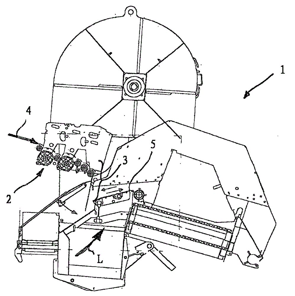
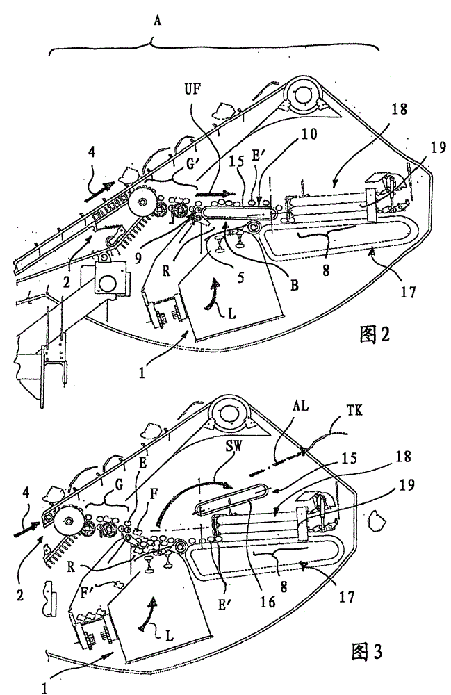
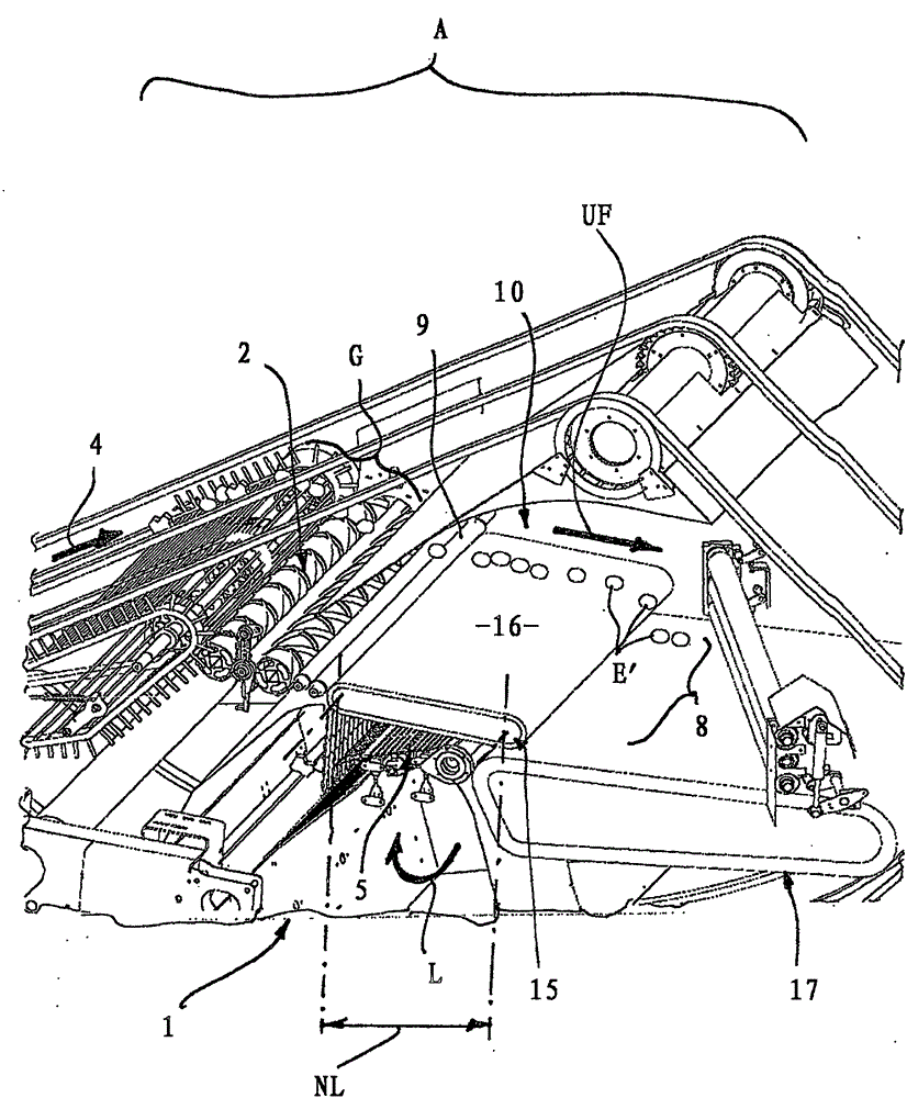
[0033] figure 1 A prior art separation device 1 is shown, according to figure 2 It is shown integrated into a potato harvester A. Such a separating device 1 is used to separate potatoes or similar crops E from a mixture G with clods, mud and other solids F. In this system, the mixture G is supplied as a conveying stream 4 from a receiving area of ​​the machine A (not further shown) by means of a conveying device indicated generally at 2 . After this conveying section, the mixture G reaches the drop 3 ( figure 1 ) area from which the gradually loosened mixture G moves onto the blocking element 5 in the area of ​​the separating device. In this area the basic constituents of the actual "sorting" of the mixture G, where the crop E' and the solids F' are further guided separately in corresponding substantially opposite conveying directions (arrows 6, 7; Figure 5 ). The separation process is supported by an air flow L generated by means of an external blower (not shown), so t...


PUM


Abstract

A separating device for separating a crop from a mixture with admixtures has a drop stage and a conveying device supplying the mixture in a conveyed stream to the drop stage. An air stream is supplied to the drop stage, wherein the mixture is falling in the drop stage and is affected by the air stream, wherein the drop stage effects loosening of the mixture. A retaining element is arranged downstream of the drop stage so as to face the mixture falling in the drop stage. The air stream interacts with the retaining element. Downstream of the retaining element the crop and solid bodies separated from the mixture are transported farther as separated individual parts in substantially opposite conveying directions. A diverting device is provided that can at least partially divert the conveyed stream upstream of the retaining element.

Description

technical field [0001] The invention relates to a potato harvester, which is designed with a separating device according to the preamble of claim 1 for separating the harvested crop from clods, stones, stalks or similar entrained debris. Background technique [0002] Machines for processing root crops, in particular potato harvesters, are known in different variants. In order to separate crops such as potatoes from clods, stones and similar solid or fibrous mixtures, different types of mechanical separators in the form of belts or screens are used (Grimme Agricultural Machinery AG, Damme; "Product Outline", GEN.00283, 08 / 13 / 5000; Harvesting Techniques, pp. 14-23). [0003] According to a solution according to DE 10 2012 016 057 A1, for the treatment of the mixture harvested by the potato harvester, an additional air flow is introduced which acts in the region of the barrier element on the separating material conveyed by the conveyor belt via the drop. The air flow is direc...

Claims


Application Information

Patent Timeline
IPC IPC(8): A01D33/04
CPCB07B9/00A01D33/02A01D33/04A01D33/08
Inventor F-J·德特默C·多曼
Owner GRIMME LANDMASCHFAB
Why Eureka
Try Eureka