Supercharge Your Innovation With Domain-Expert AI Agents!

Automatic rotary cutting device for thin-wall pipe fittings and rotary cutting method with automatic rotary cutting device

A technology of rotary cutting device and pipe fittings, which is applied in the direction of pipe shearing device, shearing device, shearing machine equipment, etc., can solve the problems of unsuitable fixture structure and tool shape, labor-intensive, low degree of automation, etc., and achieves the structure and control method. The effect of optimizing, avoiding environmental pollution, and reducing labor costs

Active Publication Date: 2015-12-09
HEFEI UNIV OF TECH
View PDF5 Cites 15 Cited by
  • Summary
  • Abstract
  • Description
  • Claims
  • Application Information

AI Technical Summary

Problems solved by technology

[0002] At present, the existing domestic pipe cutting machines have the following disadvantages: loading and unloading needs to be done manually, which consumes a lot of labor, the degree of automation is low, the work efficiency cannot meet the production needs, and the operator needs to visually measure the length of the material when loading. The error is large, resulting in a low pass rate of the product, which cannot meet the high-precision pipe fitting production
In addition, there is no special tool for thin-walled metal pipe fittings, and more chips are often generated during cutting, resulting in waste of materials and environmental pollution
There is no special fixture for thin-walled metal pipe fittings, and the deformation of thin-walled metal pipes is often caused during the tightening process of pipe fittings
The length of the pipe cutting is not adjustable, the fixture and the cutter are fixed, and the length of the part cannot be adjusted at will according to the requirements of the part. The product is single and cannot meet the market demand.
The current cutting process produces a large amount of chips, resulting in material waste and environmental pollution
[0003] In the patent document with the application number 201110083905.6, "A Fully Automatic Pipe Cutting Machine" is disclosed. This machine has been upgraded automatically for the pipe cutting machine, but because the structure of the fixture and the shape of the cutter are not suitable, it is easy to squeeze the thin-walled pipe. Compression deformation, resulting in high scrap rate, so it cannot be applied to the cutting of thin-walled pipe fittings, and the various working steps cannot be automatically connected, the degree of automation is still not enough, and the cost is too high

Method used


Image

  • Automatic rotary cutting device for thin-wall pipe fittings and rotary cutting method with automatic rotary cutting device
  • Automatic rotary cutting device for thin-wall pipe fittings and rotary cutting method with automatic rotary cutting device
  • Automatic rotary cutting device for thin-wall pipe fittings and rotary cutting method with automatic rotary cutting device

Examples


Embodiment Construction

[0034] An embodiment of the present invention will be further described below in conjunction with the accompanying drawings.

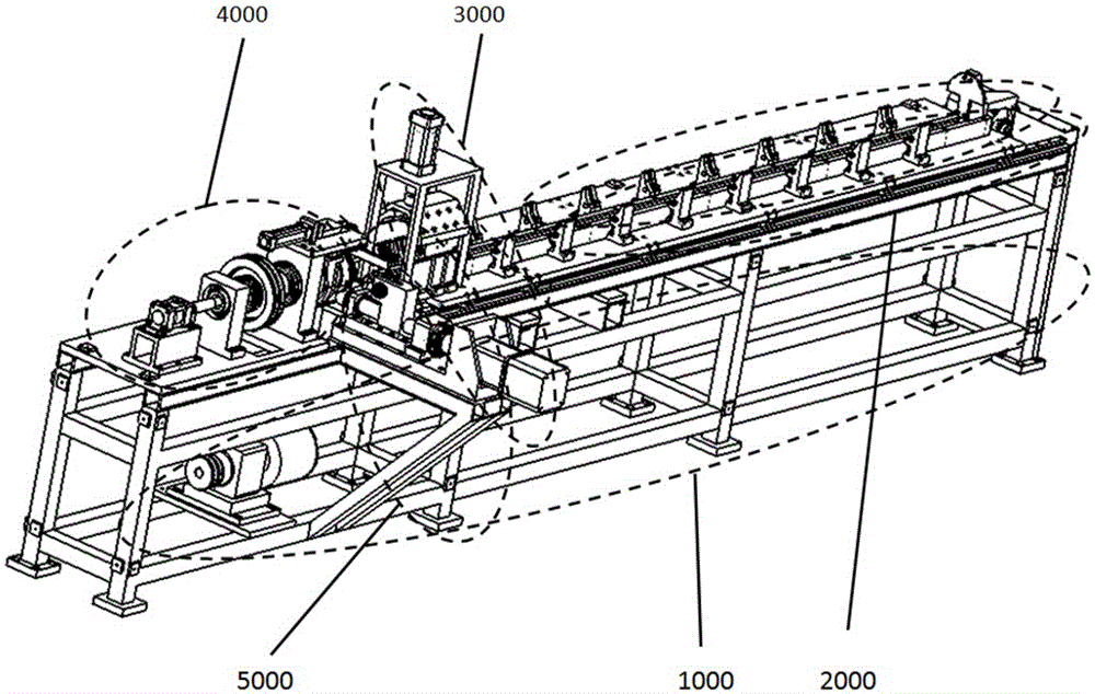
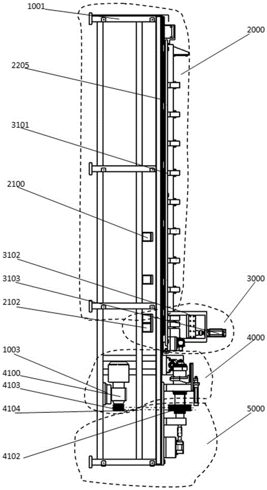
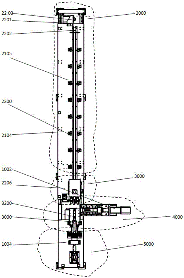
[0035] see figure 1 , an automatic rotary cutting device for thin-walled pipes, including a bracket platform assembly 1000 , a feeding assembly 2000 , a clamping assembly 3000 , a rotary cutting assembly 4000 and a feeding assembly 5000 .

[0036] The support platform assembly 1000 is a rectangular block and is fixedly installed on the foundation.

[0037] A feeding assembly 2000 is provided on one end of the support platform assembly 1000 . Note that the end of the loading assembly 2000 is the tail of the support platform assembly 1000 .

[0038] At the other end of the support platform assembly 1000, that is, at the head of the support platform assembly 1000, a clamping assembly 3000 and a blanking assembly 5000 are respectively provided.

[0039] A rotary cutting assembly 4000 is installed on the support platform assembly 1000 between the feeding...


PUM


Abstract

The invention provides an automatic rotary cutting device for thin-wall pipe fittings and a rotary cutting method with the automatic rotary cutting device and aims to overcome the defects of an existing rotary cutting machine in the rotary cutting process of the thin-wall pipe fittings. The automatic rotary cutting device for the thin-wall pipe fittings comprises a support platform assembly, a feeding assembly, a clamping assembly, a rotary cutting assembly and a discharging assembly. The rotary cutting method of the automatic rotary cutting device includes five steps. The automatic rotary cutting device for the thin-wall pipe fittings and the rotary cutting method with the same have the advantages that the problems that efficiency is low, excessively waste is generated in the process of cutting the thin-wall metal pipe fittings are solved; by the adoption of the automatic rotary cutting device and the rotary cutting method, the previous production mode that the two persons operate one machine is changed to the mode that one person operates multiple machines, and the manual cost is greatly lowered.

Description

technical field [0001] The invention relates to the technical field of metal cutting equipment, in particular to an automatic rotary cutting device for thin-walled pipe fittings and a method for performing rotary cutting using the same. Background technique [0002] At present, the existing pipe cutting machines in China have the following disadvantages: loading and unloading needs to be done manually, which consumes a lot of labor, the degree of automation is low, the work efficiency cannot meet the production needs, and the operator needs to visually measure the length of the material when loading. The error is large, resulting in a low pass rate of the product, which cannot meet the high-precision pipe fitting production. In addition, there is no special tool for thin-walled metal pipe fittings, and more chips are often generated during cutting, resulting in material waste and environmental pollution. There is no special fixture for thin-walled metal pipe fittings, and t...

Claims


Application Information

Patent Timeline
IPC IPC(8): B23D21/00
Inventor 朱华炳高晨辉訾斌卫道柱占加林陈威
Owner HEFEI UNIV OF TECH
Features
  • R&D
  • Intellectual Property
  • Life Sciences
  • Materials
  • Tech Scout
  • Unparalleled Data Quality
  • Higher Quality Content
  • 60% Fewer Hallucinations
Learn More