Vertically placed two-dimensional large-stroke fast moving device for repairing micro-defects on the surface of large-aperture curved optical elements
A technology of optical components and vertical placement, applied in the field of two-dimensional large-stroke fast moving devices, can solve the problems of slow moving speed and installation error, and achieve the effect of structural optimization
- Summary
- Abstract
- Description
- Claims
- Application Information
AI Technical Summary
Problems solved by technology
Method used
Image
Examples
specific Embodiment approach 1
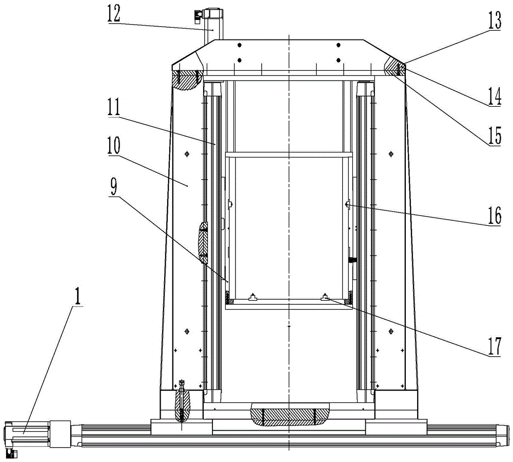
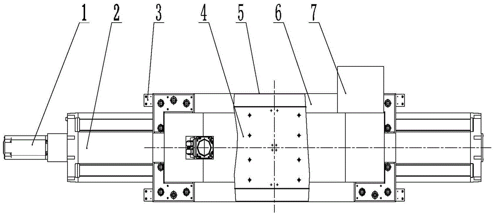
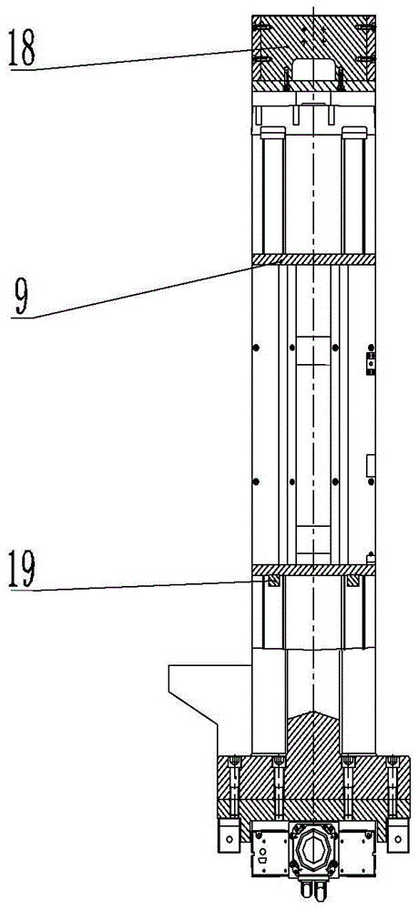
[0036] Specific implementation mode 1. Combination figure 1 , figure 2 and image 3 Describe this embodiment. The vertically placed two-dimensional large-stroke rapid moving device for repairing micro-defects on the surface of large-diameter curved optical elements described in this embodiment includes an X-axis motion unit, a gantry, a Y-axis motion unit, and a bearing frame. 9;
[0037] The X-axis motion unit includes the X-axis servo motor 1, the X-axis moving guide rail 2, the air bearing pad 3 and the bearing plate 4; the X-axis servo motor 1 is fixed on one end of the frame driving the X-axis moving guide rail 2, and the X-axis servo motor 1 drives the X-axis The axis moving guide rail 2 moves linearly in the direction of the X axis. The X axis moving guide rail 2 is equipped with a guide rail slide table. The load bearing plate 4 is fixed on the guide rail slide table. The X axis moving guide rail 2 drives the guide rail slide table to move. Pads 3 are evenly arrang...
specific Embodiment approach 2
[0044] Specific embodiment two, combine Figure 4 Describe this embodiment. This embodiment is a further description of the vertically placed two-dimensional large-stroke rapid movement device for repairing micro-defects on the surface of large-diameter curved optical elements described in Embodiment 1. The X-axis motion unit also includes a sheet metal box The upper cover 5, the lower slot 6 of the sheet metal box and the outlet box 7;
[0045] The lower slot 6 of the sheet metal box is fixed on both sides of the X-axis moving guide rail 2, the upper cover 5 of the sheet metal box is fastened on the X-axis moving guide rail 2 and the lower slot 6 of the sheet metal box, and the upper cover 5 of the sheet metal box is connected with the Between the lower grooves 6 of the sheet metal box body is a wiring trough, and the outlet box 7 is arranged on the outside of the lower groove 6 of the sheet metal box body, and the wire outlet of the outlet box 7 is aligned with the wiring gr...
specific Embodiment approach 3
[0047] Specific Embodiment 3. This embodiment is a further description of the vertically placed two-dimensional large-stroke rapid moving device for repairing micro-defects on the surface of large-diameter curved optical elements described in specific embodiment 1 or 2. The carrying frame 9 is provided with two A limit block 17, the two limit blocks 17 are fixed on the upper side of the lower frame plate of the bearing frame body 9, and the limit block 17 is used to limit the position of the device to be repaired.
[0048] The limit block described in this embodiment is used to adjust and fix the position of the optical device.
PUM
| Property | Measurement | Unit |
|---|---|---|
| torque | aaaaa | aaaaa |
| torque | aaaaa | aaaaa |
Abstract
Description
Claims
Application Information
 - R&D
- Intellectual Property
- Life Sciences
- Materials
- Tech Scout
- Unparalleled Data Quality
- Higher Quality Content
- 60% Fewer Hallucinations
Browse by: Latest US Patents, China's latest patents, Technical Efficacy Thesaurus, Application Domain, Technology Topic, Popular Technical Reports.
© 2025 PatSnap. All rights reserved.Legal|Privacy policy|Modern Slavery Act Transparency Statement|Sitemap|About US| Contact US: help@patsnap.com


