Automatic screw-driving machine with double electric screwdrivers and multiple feeders

An automatic locking screw machine and feeder technology, which is applied in metal processing, metal processing equipment, manufacturing tools, etc., can solve the problems of low practicability and inconvenient use, so as to improve work efficiency, reduce production costs, and improve The effect of flexibility

Inactive Publication Date: 2015-12-09
NEW ROAD MARK AUTOMATION TECH
View PDF6 Cites 16 Cited by
  • Summary
  • Abstract
  • Description
  • Claims
  • Application Information

AI Technical Summary

Problems solved by technology

[0002] The locking screw machine has the characteristics of reliable structure, convenient use, and is suitable for various batch operations. However, for larger products such as notebook computers, vacuum cleaners, and outdoor LED light panels, and even larger products within 350mm*600mm, two types are required. Or a variety of screws with different sizes. The existing automatic locking screw machine can only use screws of one size when working. If it needs to lock another size, it needs to be readjusted. When the components are adjusted, professional programmers are often required to compile, and the practicability is low

Method used


Image

  • Automatic screw-driving machine with double electric screwdrivers and multiple feeders
  • Automatic screw-driving machine with double electric screwdrivers and multiple feeders
  • Automatic screw-driving machine with double electric screwdrivers and multiple feeders

Examples


Embodiment Construction

[0018] The present invention will be described in further detail below in conjunction with the accompanying drawings.

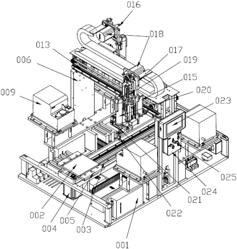
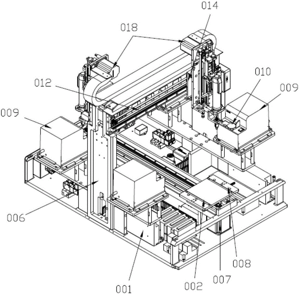
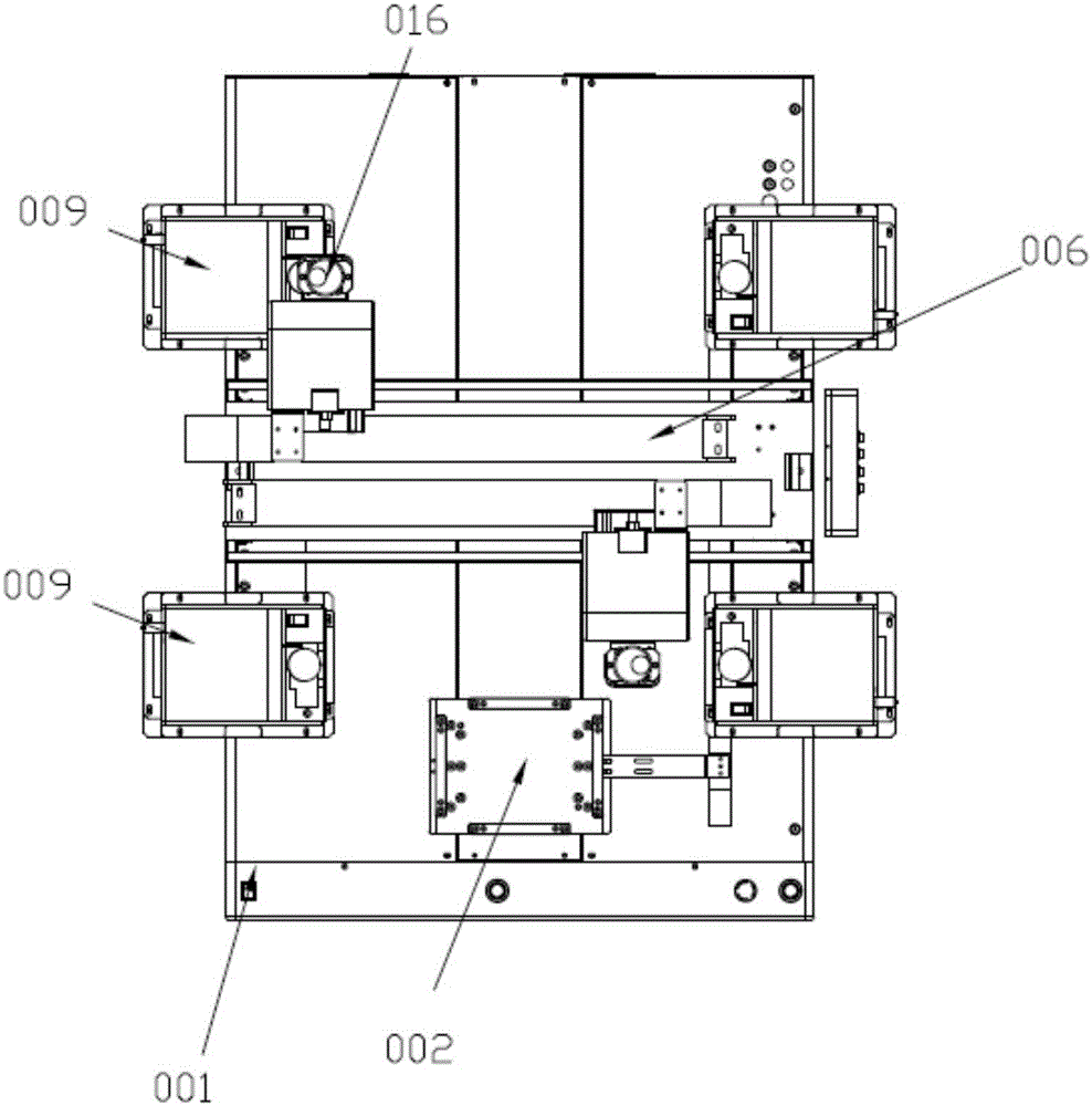
[0019] Figure 1 to Figure 4 It schematically shows a double electric batch multi-feeder automatic screw locking machine according to the present invention.

[0020] This embodiment provides a double electric batch multi-feeder automatic locking screw machine, please refer to Figure 1 to Figure 3 , including a machine base 001, a Y-axis moving mechanism is provided in the middle of the machine base 001, and two sets of clamps 002 are arranged on the Y-axis moving mechanism, specifically, the Y-axis moving mechanism includes The third linear slide rail 003 on 001, the first Y-axis stepping motor 004 and the second Y-axis stepping motor 007 with large torque, and the third linear slide rail 003 is provided with the Y-axis stepping motor 004. The third slider 005 and the fourth slider 008 connected with the Y-axis stepping motor 007, the two sets of clamps 00...


PUM


Abstract

The invention discloses an automatic screw-driving machine with double electric screwdrivers and multiple feeders. The automatic screw-driving machine comprises a machine base; a Y-axis moving mechanism is arranged in the middle of the machine base and provided with two sets of clamps; a cross beam is arranged on the machine base and located above the middle of the Y-axis moving mechanism; at least two sets of symmetrical screw feeding mechanisms are arranged on the left and right sides of each of the head end and the tail end of the Y-axis moving mechanism; an X-axis moving mechanism is arranged on the cross beam, and two sets of locking mechanisms are arranged on the front and rear sides of the X-axis moving mechanism and are oppositely arranged; each set of locking mechanism comprises a locking fixing seat connected with the X-axis moving mechanism, and a Z-axis moving mechanism is arranged on each locking fixing seat and sequentially connected with a flexible device, one electric screwdriver, a screwdriver head and a suction nozzle component; a handheld type operation control system is arranged on one side of the cross beam. According to the automatic screw-driving machine, manual operation is replaced with an automatic mode, so that the work efficiency is improved, the production cost is lowered, operation is reliable, and the assembling precision is high.

Description

technical field [0001] The invention relates to the field of automation equipment, in particular to an automatic screw locking machine with double electric batches and multiple feeders. Background technique [0002] The locking screw machine has the characteristics of reliable structure, convenient use, and is suitable for various batch operations. However, for larger products such as notebook computers, vacuum cleaners, and outdoor LED light panels, and even larger products within 350mm*600mm, two types are required. Or a variety of screws with different sizes. The existing automatic locking screw machine can only use screws of one size when working. If it needs to lock another size, it needs to be readjusted. When the components are adjusted, professional programmers are often required to compile, and the practicability is low. Contents of the invention [0003] The object of the present invention is to provide an automatic locking screw machine with double electric bat...

Claims


Application Information

Patent Timeline
Patent Type & Authority Applications(China)
IPC IPC(8): B23P19/06
CPCB23P19/069
Inventor 彭陆春陈俊志
Owner NEW ROAD MARK AUTOMATION TECH
Why Eureka
Try Eureka