Disassembly tool for oil drain plug of engine oil bottom shell

A technology for engine oil and dismantling tools, which is applied in the manufacture of tools and hand-held tools, can solve problems such as low work efficiency, long waiting time, and long disassembly time, and achieve the effects of improving work efficiency, strong practicability, and low cost

Active Publication Date: 2015-12-09
CHONGQING CHANGAN AUTOMOBILE CO LTD
View PDF5 Cites 9 Cited by
  • Summary
  • Abstract
  • Description
  • Claims
  • Application Information

AI Technical Summary

Problems solved by technology

[0002] CN202517439U discloses a screw plug dismounting tool, which is used to disassemble the screw plug in the mechanical torque wrench, but it is not suitable for dismounting the oil drain plug on the engine oil pan
These two disassembly methods have the following problems: (1) When the oil drain plug is loosened and removed directly with a wrench or a sleeve, the oil drain plug is easy to fall into the oil basin, and the oil drain plug from the oil basin It is inconvenient to take out the screw plug. The high-temp

Method used


Image

  • Disassembly tool for oil drain plug of engine oil bottom shell
  • Disassembly tool for oil drain plug of engine oil bottom shell
  • Disassembly tool for oil drain plug of engine oil bottom shell

Examples


Example Embodiment

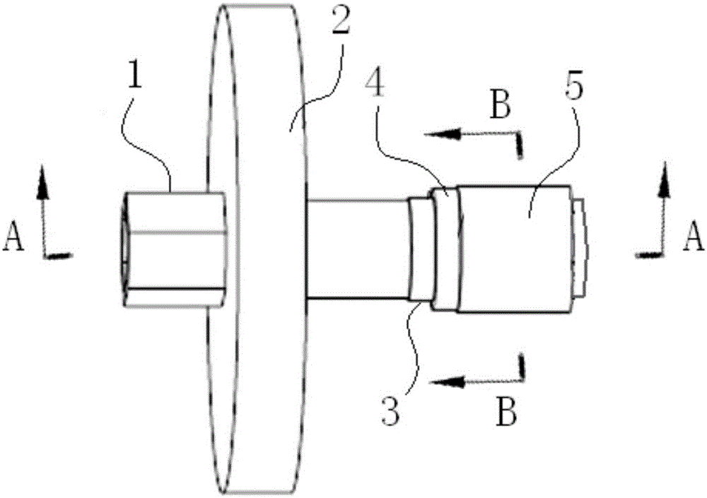
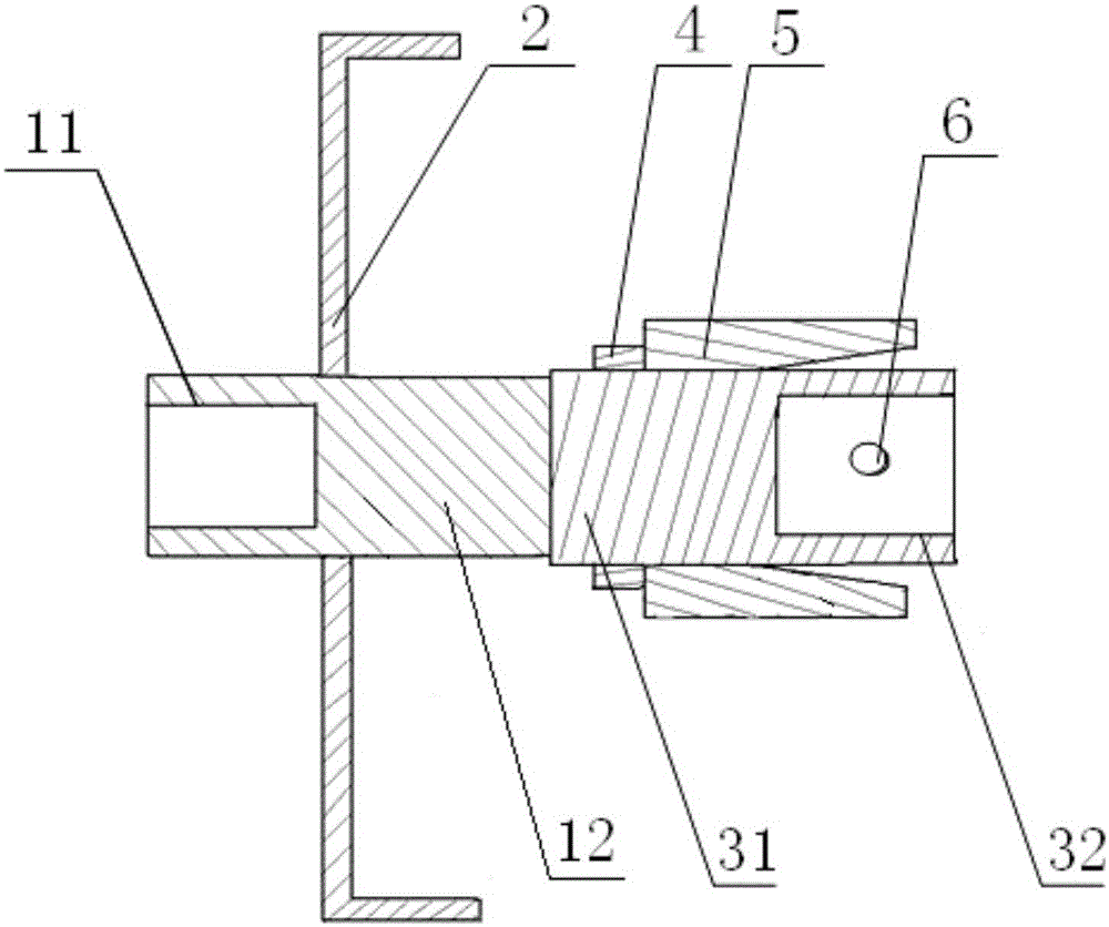
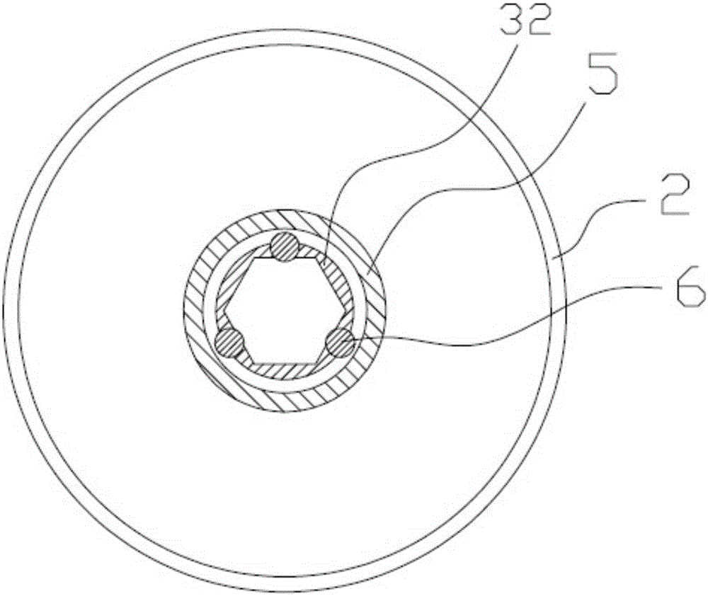
[0020] Example 1: Such as Figure 1 to Figure 3 The shown removal tool for the oil drain plug of the engine oil pan includes a handle 1, an oil baffle plate 2, a screw plug sleeve 3, a limit stop ring 4 and a lock ring 5; the oil baffle plate 2 has a bent edge The handle 1 passes through the center of the oil damper 2 and is welded to the oil damper 2. The part of the handle 1 on the left side of the oil damper 2 is a hexagon nut 11, and the part of the handle 1 on the right of the oil damper 2 is Connecting cylinder 12; the left part of the screw plug sleeve 3 is a stud 31, the right part of the screw plug sleeve 3 is a hexagonal sleeve 32, the left end of the stud 31 is welded to the right end of the connecting cylinder 12, the spacing of the hexagonal sleeve 32 There is a round hole on each of the three inner walls (a total of three round holes, the angle between two adjacent round holes is 120°), and each round hole is embedded with a steel ball 6 (a total of three steel ba...

Example Embodiment

[0027] Example 2: See Figure 5 The structure of the removal tool for the oil drain plug of the engine oil pan is mostly the same as that of the first embodiment. The difference is that a round hole is provided on each of the six inner walls of the hexagonal sleeve 32 (a total of six round holes , The angle between two adjacent round holes is 60°), each round hole is embedded with a steel ball 6 (a total of six steel balls).


PUM


Abstract

The invention discloses a disassembly tool for an oil drain plug of an engine oil bottom shell. The disassembly tool comprises a handle, a plug sleeve, an oil baffle disc and a locking ring, wherein the handle penetrates through the center of the oil baffle disc and is fixedly connected with the oil baffle disc; the part, positioned at the left side of the oil baffle disc, of the handle is a hexagonal nut; the part, positioned at the right side of the oil baffle disc, of the handle is a connecting cylinder; the left end of the plug sleeve is fixedly connected with the right end of the connecting cylinder; a stud is arranged on the left part of the plug sleeve; a hexagonal sleeve is arranged on the right part of the plug sleeve; a circular hole is formed in the inner wall of the hexagonal sleeve; a steel ball is embedded into the circular hole; the left part of the locking ring is provided with an inner threaded hole; the right part of the locking ring is provided with a tapered hole which is gradually increased in diameter from left to right, and communicates with the inner threaded hole; the locking ring penetrates through the hexagonal sleeve and is screwed on the stud through threads; the wall surface of the tapered hole can generate extrusion effect on the steel ball and can restrain the steel ball from dropping. The disassembly tool not only can prevent an oil drainage plug from dropping into an oil basin, but also can prevent hands of an operator from being burnt, and further can improve the working efficiency.

Description

technical field [0001] The invention relates to a dismantling tool for auto parts, in particular to a dismantling tool for an oil drain screw plug of an engine oil pan. Background technique [0002] CN202517439U discloses a screw plug dismounting tool, which is used to disassemble the screw plug in the mechanical torque wrench, but it is not suitable for dismounting the oil drain plug on the engine oil pan. [0003] At present, when the oil drain plug on the engine oil pan is disassembled, the usual methods are: (1) dismantling with a wrench, and (2) dismantling through a sleeve with a handle. These two disassembly methods have the following problems: (1) When the oil drain plug is loosened and removed directly with a wrench or a sleeve, the oil drain plug is easy to fall into the oil basin, and the oil drain plug from the oil basin It is inconvenient to take out the screw plug. The high-temperature oil will burn the operator's hands. It is necessary to wait until the oil c...

Claims


Application Information

Patent Timeline
IPC IPC(8): B25B27/14
CPCB25B27/0042B25B27/14
Inventor 先大伟蒋欣雨江宝宇郝栋陈松林
Owner CHONGQING CHANGAN AUTOMOBILE CO LTD
Why Eureka
Try Eureka