Hydraulic lifting chain stamping machine and printing method thereof

An embossing machine, hydraulic technology, applied in the field of embossing machines, can solve the problems of low efficiency, high labor consumption, high production cost, etc.

Active Publication Date: 2015-12-09
HANGZHOU ZHEZHONG CHAIN
View PDF5 Cites 1 Cited by
  • Summary
  • Abstract
  • Description
  • Claims
  • Application Information

AI Technical Summary

Problems solved by technology

[0002] The chain zippers in the prior art are all manually operated, and the embossing machine needs two people to operate, one person is responsible for loading the material, and the manual is responsible for pulling the material. The labor consumption is high, the efficiency is low, and the production cost is high.

Method used


Image

  • Hydraulic lifting chain stamping machine and printing method thereof
  • Hydraulic lifting chain stamping machine and printing method thereof
  • Hydraulic lifting chain stamping machine and printing method thereof

Examples


Embodiment 1

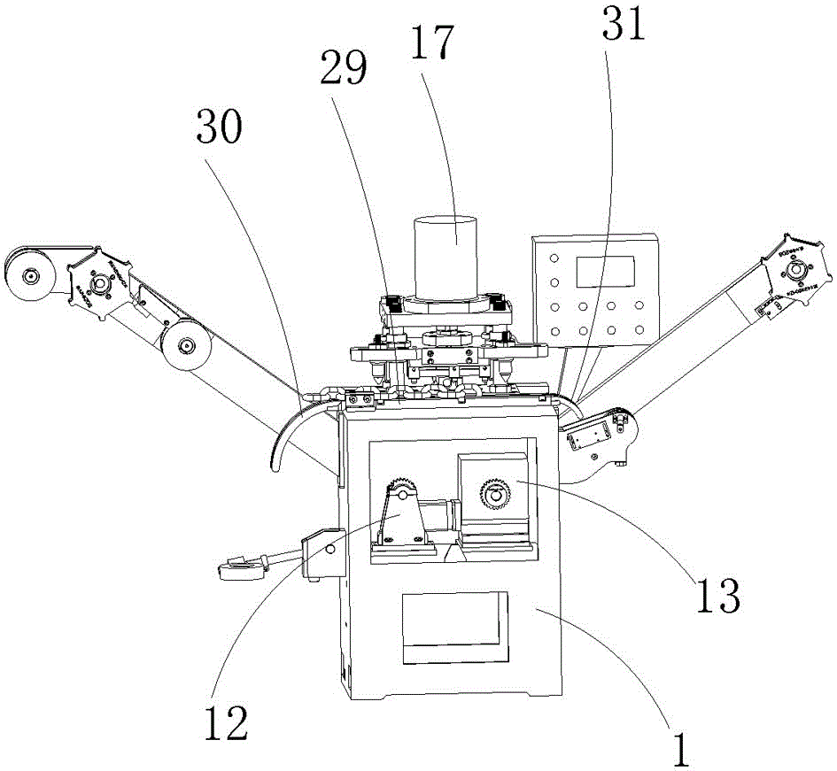
[0050] Embodiment 1: as figure 1 , figure 2 , image 3 , Figure 4 , Figure 5 , Image 6 , Figure 7 , Figure 8 , Figure 9 , Figure 10 , Figure 11 , Figure 12 , Figure 12 with Figure 13As shown, a hydraulic lifting chain embossing machine includes an operating frame 1, the left end of the operating frame 1 is provided with a pre-feeding mechanism, and the right end of the operating frame 1 is provided with a pre-feeding mechanism. The feeding mechanism corresponds to the chain discharging mechanism, the operation frame 1 is provided with a drag chain transmission mechanism and a printing action mechanism, and the drag chain transmission mechanism and the printing action mechanism are in a corresponding distribution;

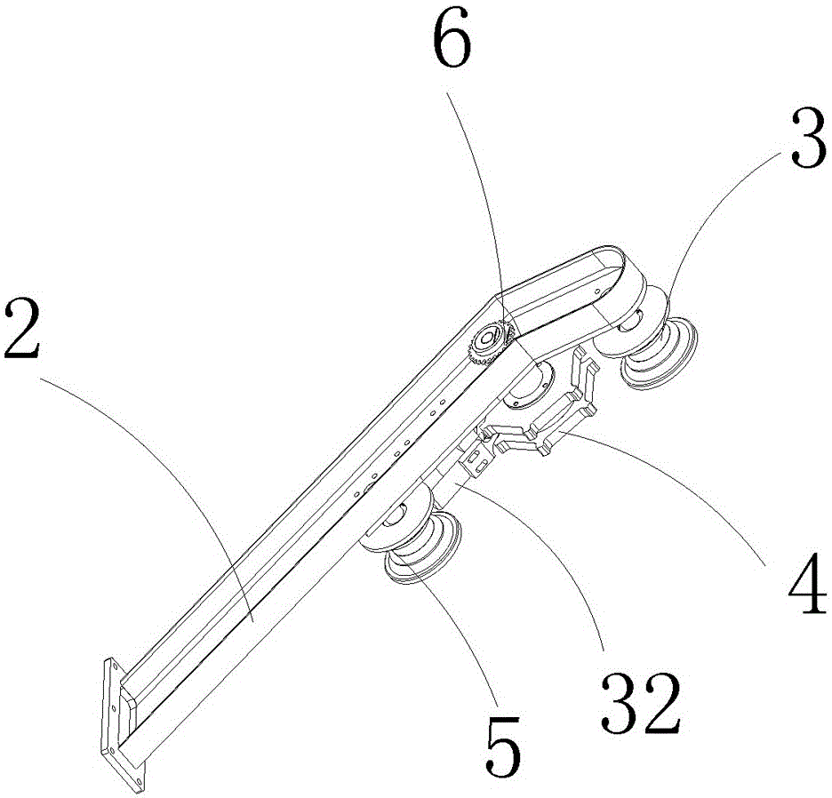
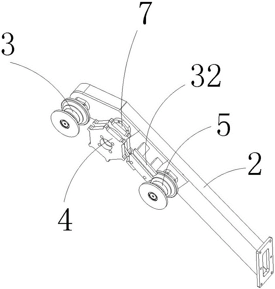
[0051] Described pre-feeding mechanism comprises feed channel steel 2, and the afterbody of described feed channel steel 2 is fixed with operating frame 1, and the upper end of described feed channel steel 2 is provided with upper guide sproc...


PUM


Abstract

The invention relates to a stamping machine, in particular to a hydraulic lifting chain stamping machine and a printing method thereof. The stamping machine comprises an operation frame, wherein a prefeeding mechanism is arranged at the left side end of the operation frame; a walking chain discharge mechanism corresponding to the prefeeding mechanism is arranged at the right side end of the operation frame; a drag chain transmission mechanism and a printing action mechanism are arranged in the operation frame; and the drag chain transmission mechanism and the printing action mechanism are correspondingly distributed. The printing method is performed by the steps of: chain walking-positioning-steel mark depth adjustment-chain discharge-quality inspection. The hydraulic lifting chain stamping machine and the printing method thereof are simple in structure, realize automatic loading, automatic steel sealing and automatic unloading, improve the working efficiency, and reduce the labor intensity of workers.

Description

technical field [0001] The invention relates to a stamping machine, in particular to a hydraulic lifting chain stamping machine and a printing method thereof. Background technique [0002] The chain zippers in the prior art are all manually operated, and the embossing machine requires two people to operate, one person is responsible for loading materials, and the manual is responsible for pulling materials, which has high labor consumption, low efficiency, and high production costs. Contents of the invention [0003] The present invention mainly solves the deficiencies in the prior art, and provides a highly compact structure, according to different chain specifications, through different tooling fixtures, according to mechanical and hydraulic working principles, driven by servo motors or hydraulic motors, pre-feeding The material mechanism drags the chain to be calibrated into the embossing area to carry out the embossing work of the steel stamp mark. After the embossing ...

Claims


Application Information

Patent Timeline
Patent Type & Authority Applications(China)
IPC IPC(8): B41K3/04B41K3/62B41M1/12
Inventor 朱四华
Owner HANGZHOU ZHEZHONG CHAIN
Why Eureka
Try Eureka