Hydraulic driving generator energy-saving power generation system

An energy-saving power generation and generator technology, which is applied to vehicle components, control devices, auxiliary drive devices, etc., can solve the problems of unit efficiency reduction, power waste, and engine output power mismatch, so as to improve unit efficiency and ensure operability performance, energy-saving operation and continuous power generation

Active Publication Date: 2018-01-23
YANSHAN UNIV
View PDF6 Cites 0 Cited by
  • Summary
  • Abstract
  • Description
  • Claims
  • Application Information

AI Technical Summary

Problems solved by technology

[0007] The purpose of the present invention is to provide an energy-saving power generation system for a hydraulic type driving generator to overcome the power waste and unit failure caused by the incompatibility between the power obtained by the hydraulic type driving generator from the engine and the output power of the engine in the prior art. Efficiency reduction and other issues

Method used


Image

  • Hydraulic driving generator energy-saving power generation system
  • Hydraulic driving generator energy-saving power generation system

Examples


Embodiment Construction

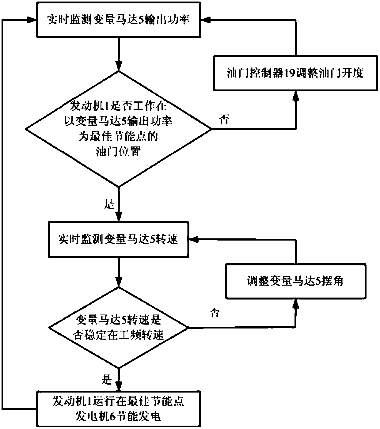
[0020] Embodiments of the present invention will be further described in detail below in conjunction with the accompanying drawings and examples. The following examples are used to illustrate the present invention, but should not be used to limit the scope of the present invention.

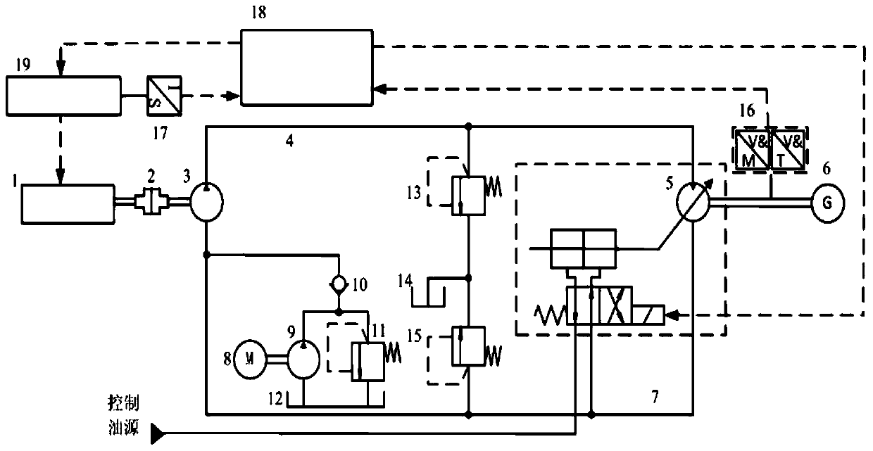
[0021] Such as figure 1 As shown, the hydraulic driving generator energy-saving power generation system of this embodiment includes: engine 1, coupling 2, quantitative pump 3, high-pressure oil circuit 4, variable motor 5, generator 6, low-pressure oil circuit 7, oil-charging motor 8. Charging pump 9, one-way valve 10, overflow valve 11, fuel tank 12, high pressure safety valve 13, fuel tank 14, low pressure safety valve 15, speed torque sensor 16, displacement sensor 17, calculation controller 18, throttle controller 19.

[0022] The engine 1 is coaxially connected with the quantitative pump 3 through the coupling 2, and is used to convert mechanical energy into hydraulic energy; the oil suctio...


PUM


Abstract

The invention relates to the technical field of on-board power generation, and specifically discloses a hydraulic on-board generator energy-saving power generation system, comprising an engine, a coupling, a quantitative pump, a high-pressure oil circuit, a variable motor, a generator, a low-pressure oil circuit, and a rotational speed torque sensor , displacement sensor, calculation controller and throttle controller, the engine is coaxially connected to the quantitative pump through the coupling, the oil suction port of the quantitative pump is connected to the low-pressure oil circuit, and the pressure oil port of the quantitative pump is connected to the variable motor through the high-pressure oil circuit. The oil discharge port of the variable motor is connected to the low-pressure oil circuit, the variable motor is coaxially connected to the generator, the speed and torque sensor is set between the variable motor and the generator, the displacement sensor is set on the throttle controller of the engine, and the calculation controller is respectively Connected to displacement sensor, rotational speed torque sensor, throttle controller and variable motor. The invention can make the output power of the engine match the power obtained by the generator, avoid power waste, and effectively improve the efficiency of the unit.

Description

technical field [0001] The invention relates to the technical field of driving power generation, in particular to a hydraulic driving generator energy-saving power generation system. Background technique [0002] With the development of power electronics technology and frequency conversion speed regulation technology, electronic equipment is widely used in military equipment such as armored vehicles, tanks, and mobile equipment such as agricultural machinery, which makes mobile machinery more and more demanding on electricity, especially for Mobile power needs. The mobile power supply is also more in line with the characteristics of strong mobility and uncertainty in modern warfare, so it has attracted the attention of many countries, and has given great attention and strong support to the research and development of driving power generation technology. [0003] Driving power generation means that the vehicle can drive the generator to generate power during driving, in addi...

Claims


Application Information

Patent Timeline
Patent Type & Authority Patents(China)
IPC IPC(8): B60K25/06
Inventor 艾超刘艳娇孔祥东闫桂山
Owner YANSHAN UNIV
Why Eureka
Try Eureka