
Oil collection device for kitchen wastewater

A technology of kitchen waste water and grease trap, applied in the direction of grease/oily substance/floating matter removal device, liquid separation, separation method, etc., can solve the problems of difficult oil collection in ship grease trap, and achieve novel design, exquisite structure, The effect of low cost

Inactive Publication Date: 2015-12-09
ZHONGCHUAN NO 9 DESIGN & RES INST
View PDF7 Cites 4 Cited by
  • Summary
  • Abstract
  • Description
  • Claims
  • Application Information

AI Technical Summary

Problems solved by technology

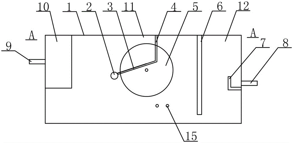
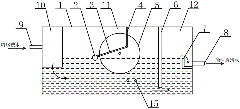
[0004] The object of the present invention is an oil collection device for kitchen waste water designed for the deficiencies of the prior art, which uses a turntable to capture floating oil in the water, and uses an oil scraper to collect the dirty oil adhered to the turntable into the oil collection tank and flow out of the oil separation tank. Realize the automatic separation of slick oil in kitchen waste water, simple structure, high oil-water separation efficiency, convenient equipment maintenance, low operation and maintenance costs, especially suitable for the recovery of water and oil in various restaurants, canteens including luxury cruise restaurants, and provide for the subsequent treatment of sewage Guarantee, better solve the technical problem of difficult oil collection in the ship's oil trap

Method used


Image

  • Oil collection device for kitchen wastewater
  • Oil collection device for kitchen wastewater
  • Oil collection device for kitchen wastewater

Examples


Embodiment Construction

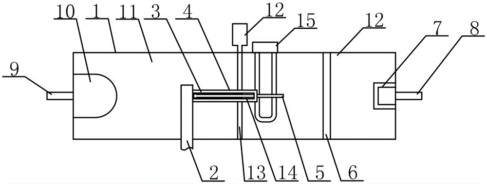
[0011] See attached figure 1 ~ attached figure 2 , the present invention is composed of an oil wiper 3 and a turntable 5 arranged in an oil separation tank 1. The oil separation tank 1 is separated by a baffle plate 6 into an oil-water separation chamber 11 and a water outlet chamber 12 connected to the left and right lower parts. The oil-water separation chamber 11 The tank body on one side is provided with the water inlet pipe 9 of the mesh basket 10, and the water outlet pipe 8 provided with the weir plate 7 is arranged on the tank body of the water outlet chamber 12 side; Inside, one end of the rotating shaft 5 is connected to the motor 12 arranged outside the tank; the oil scraper 3 is a "U"-shaped scraper with an oil collection tank 2 at one end, and the "U"-shaped scraper is arranged on both sides of the turntable 5 by the bracket 4. The outlet of the oil collecting tank 2 is arranged outside the tank, the "U" shaped scraper is fixedly connected with the support 4, an...


PUM


Abstract

The invention discloses an oil collection device for kitchen wastewater. The oil collection device is characterized by being composed of an oil wiper and a rotating plate arranged in an oil isolation tank, the oil isolation tank is divided by a baffle into an oil-water separation chamber and a water outlet chamber with the lower portions communicated, a water inlet pipe of a mesh basket is arranged on the portion, on one side of the oil-water separation chamber, of a tank body, a water outlet pipe provided with a weir plate is arranged on the portion, on one side of the water outlet chamber, of the tank body, the rotating plate is arranged in the oil-water separation chamber through a rotating shaft, one end of the rotating shaft is connected with a motor arranged outside the tank body, the oil wiper is a U-shaped scraper with one end provided with an oil collection tank, the U-shaped scraper is arranged on the two sides of the rotating plate through a support, the outlet of the oil collection tank is formed outside the tank body, and the U-shaped wiper is fixedly connected with the support. Compared with the prior art, the oil collection device is novel in design, exquisite in structure, low in manufacturing cost, convenient to operate and high in oil, water and residue separation efficiency, the device maintenance is convenient, the operating cost is low, and the oil collection device is a device which is wide in application range, capable of saving energy and reducing emission and environmentally friendly.

Description

technical field [0001] The invention relates to the technical field of oil-water separation equipment, in particular to an oil collecting device for kitchen waste water. Background technique [0002] With the improvement of people's living standards, the catering industry is increasingly developed, and the amount of catering wastewater continues to increase. According to national standards, catering wastewater needs to be discharged into the urban sewage pipe network after decontamination. The degreasing pretreatment of catering wastewater has always been a concern of people. If this part of dirty oil is not managed properly, it will flow into the waste oil to create harmful society. Generally, kitchen and catering wastewater is treated with a grease trap to remove floating oil. The grease trap is a stainless steel tank with two baffles. The dirty oil floats to the surface in the tank and is blocked by the baffles. The dirty oil is generally removed from the surface manually...

Claims


Application Information

Patent Timeline
Patent Type & Authority Applications(China)
IPC IPC(8): C02F1/40
Inventor 葛梅胡青沈波蔡治平王继荣
Owner ZHONGCHUAN NO 9 DESIGN & RES INST
Learn More