
Corrugated steel web few-main-beam structure

A corrugated steel web and beam structure technology, which is applied to bridges, bridge parts, bridge construction, etc., can solve the problems of large amount of formwork engineering and on-site wet work, the impact of existing urban traffic, and the relatively large impact of the surrounding environment. Achieve the effect of reducing the amount of concrete, shortening the construction period and speeding up the construction

Inactive Publication Date: 2015-12-09
HENAN DAJIAN BRIDGE STEEL STRUCTURE
View PDF7 Cites 8 Cited by
  • Summary
  • Abstract
  • Description
  • Claims
  • Application Information

AI Technical Summary

Problems solved by technology

[0003] The existing bridge buildings have the following deficiencies: 1. In recent years, engineering practice has found that after a period of operation of concrete beams, the mid-span of the beam body continues to deflect, and the web cracks and other diseases are more prominent. When the design service life is not reached, it needs to be reinforced and reconstructed; 2. During the construction of the cast-in-place concrete bridge deck, formwork needs to be set up, and then concrete is poured on site on the formwork. However, the amount of form work and on-site wet work is large, and the construction speed is slow. When the formwork cannot be fully supported by steel beams, it is necessary to set up a full floor of scaffolding. The construction cost is high and has a great impact on the surrounding environment.
[0004] Due to the long construction period of the existing bridges, most of the existing construction techniques have to occupy roads for construction, especially the traditional support construction method has high overall energy consumption and a large amount of manual work on site, which has a serious impact on the existing traffic in the city

Method used


Image

  • Corrugated steel web few-main-beam structure
  • Corrugated steel web few-main-beam structure
  • Corrugated steel web few-main-beam structure

Examples


Embodiment 1

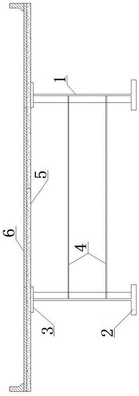
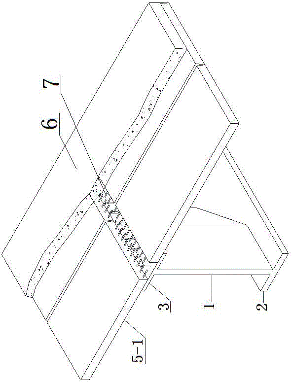
[0036] The prefabricated segmental bridge deck structure of corrugated steel web less main girder bridge, including multiple corrugated steel web girders, the prefabricated segmental bridge deck 5-1 set on the corrugated steel web, the prefabricated segmental bridge deck 5-1 The upper pavement is provided with a bridge deck pavement layer 6;

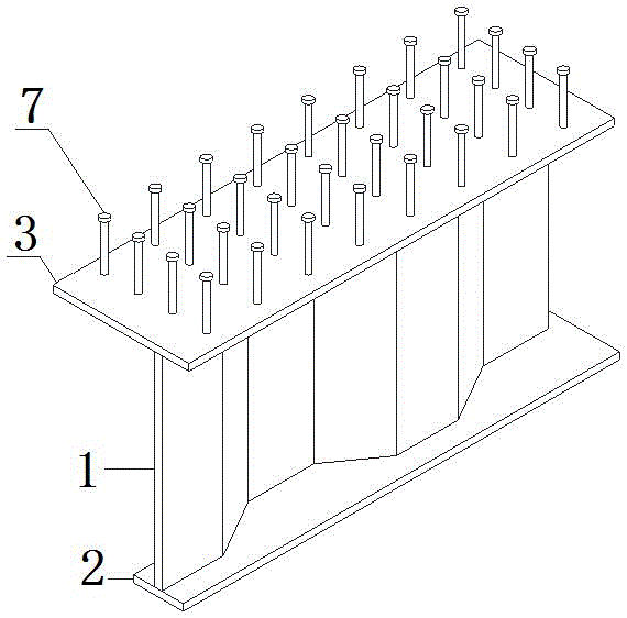
[0037] The corrugated steel web girder comprises a corrugated steel web 1, a lower flange steel plate 2 arranged below the corrugated steel web 1 and an upper flange steel plate 3 arranged above the corrugated steel web 1; the corrugated The steel web 1 is welded to the upper flange steel plate 3 and the lower flange steel plate 2 respectively; the lower flange steel plate 2 at the support is a thickened steel plate;

[0038] The upper flange steel plate 3 is provided with a plurality of stud groups 7, and the studs forming the stud group 7 are arranged intermittently; the upper flange steel plate 3 and the plurality of stud groups 7 are...

Embodiment 2

[0040] The overall prefabricated bridge deck structure of the corrugated steel web less main girder bridge includes multiple corrugated steel web girders, the prefabricated integral concrete bridge deck 5-2 set on the corrugated steel web, and the prefabricated integral concrete bridge deck 5-2 A bridge deck pavement layer 6 is laid;

[0041] The corrugated steel web girder comprises a corrugated steel web 1, a lower flange steel plate 2 arranged below the corrugated steel web 1 and an upper flange steel plate 3 arranged above the corrugated steel web 1; the corrugated The steel web 1 is welded to the upper flange steel plate 3 and the lower flange steel plate 2 respectively; the lower flange steel plate 2 at the support is a thickened steel plate;

[0042] The upper flange steel plate 3 is provided with a plurality of stud groups 7, and the studs forming the stud group 7 are arranged intermittently; the upper flange steel plate 3 and the plurality of stud groups 7 are welded ...


PUM


Abstract

The invention discloses a corrugated steel web few-main-beam structure which comprises a plurality of corrugated steel web main beams, a concrete prefabricated plate arranged on corrugated steel webs, and a bridge deck pavement layer is laid on the concrete prefabricated plate. According to the corrugated steel web few-main-beam structure, a corrugated steel web combined structure is adopted, the use efficiency of steel and concrete materials is fully developed, the use amount of concrete is reduced, the dead load of the main beams is reduced, energy conservation and environmental friendliness are achieved, and the economic performance is good. Structural key parts of the corrugated steel web main beams and a concrete bridge deck slab are factorized, the concrete bridge deck slab is prefabricated in a factory and can reduce the additional stress caused by shrinkage and creep of the concrete, the product quality is easily ensured, and compared with a cast-in-place mode, the process of demounting and mounting a formwork is omitted, the wet work amount on the field is reduced, the construction period is shortened, and the construction progress is shortened. The smooth passing of the road can be achieved under a bridge in the construction process of the bridge, fast construction can be achieved, the influences on the existing traffic are small, and the social benefits are good. A basis is provided for factory standardized and prefabricated production and field assembly building of a 30 m-50 m corrugated steel web PC box girder bridge, and the application fields are expanded.

Description

technical field [0001] The invention relates to the field of steel-concrete composite structures, in particular to a structure with corrugated steel webs and few main girders. Background technique [0002] With the acceleration of the urbanization process, bridge construction has not yet solved the problem of traffic congestion. More and more viaducts and overpasses are being built in large and medium-sized cities in China. Bridge construction is still dominated by concrete materials. The construction methods are manual binding, Mainly cast on site. [0003] The existing bridge buildings have the following deficiencies: 1. In recent years, engineering practice has found that after a period of operation of concrete beams, the mid-span of the beam body continues to deflect, and the web cracks and other diseases are more prominent. When the design service life is not reached, it needs to be reinforced and reconstructed; 2. During the construction of the cast-in-place concrete ...

Claims


Application Information

Patent Timeline
IPC IPC(8): E01D19/00E01D19/12
Inventor 雷政马春祥赵森
Owner HENAN DAJIAN BRIDGE STEEL STRUCTURE
Learn More