
Novel high-speed lift door

A technology for lifting doors and high speed, which is applied in door/window fittings, the arrangement of wing leaves, buildings, etc. It can solve the problems of the lifting speed limit of the lifting door, the door cannot operate normally, and the wire rope is taken off, so as to increase the lifting speed and improve the Production traffic efficiency and the effect of ensuring heat dissipation loss

Inactive Publication Date: 2015-12-09
天津鸿坤巴士德科技有限公司
View PDF6 Cites 0 Cited by
  • Summary
  • Abstract
  • Description
  • Claims
  • Application Information

AI Technical Summary

Problems solved by technology

[0002] Existing lifting doors are generally driven by a rope pulley with a wire rope. The wire rope is wound on the rope pulley to drive the door body to run. The lifting speed of the lifting door is limited to a certain extent

Method used


Image

  • Novel high-speed lift door
  • Novel high-speed lift door
  • Novel high-speed lift door

Examples


Embodiment Construction

[0028] It should be noted that, in the case of no conflict, the embodiments of the present invention and the features in the embodiments can be combined with each other.

[0029] The present invention will be described in detail below with reference to the accompanying drawings and examples.

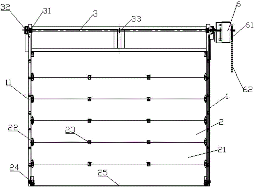
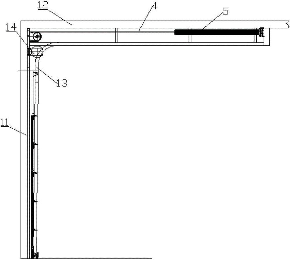
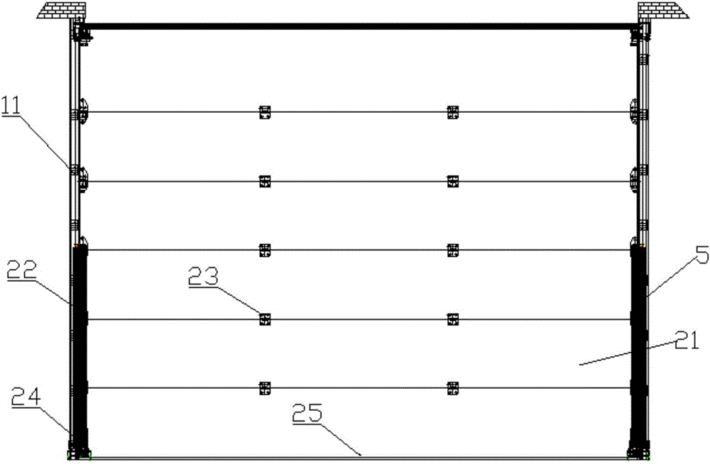
[0030] Such as Figures 1 to 3 As shown, the present invention includes a door frame 1, a door panel 2, a rotating shaft 3, a chain 4, an extension spring 5 and a power unit 6.

[0031] The door frame 1 comprises a vertical door frame 11 and a horizontal door frame 12, both sides of the vertical door frame 11 and the horizontal door frame 12 are oppositely provided with door panel slide guide rails 13, the horizontal door frame 12 is vertically fixed to the top of the vertical door frame 11, and the horizontal door frame 12 The door panel sliding guide rail 13 of the vertical door frame 11 is connected in an arc, so that the door panel 2 slides back and forth in the door panel sliding t...


PUM


Abstract

The invention provides a novel high-speed lift door which includes a door frame, a door panel, a rotating shaft, chains, a pair of tension springs and a power unit, wherein the door frame includes vertical door frames and a horizontal door frame which is perpendicular to the vertical door frames and fixed at the top ends of the vertical door frames; door panel sliding rails in smooth connection are arranged on both sides of the door frame in an opposite manner; clamping positions of the door panel are mounted in the sliding rails of the door panel; the rotating shaft is horizontally fixed at the top ends of the vertical door frames; a transmission chain wheel is fixedly arranged on each of both sides of the rotating shaft; one ends of the pair of tension springs are fixed on both sides of the tail end of the door frame, and the other ends of the tension springs are fixedly connected with one ends of the pair of chains; the other ends of the chains bypass the transmission chain wheels and are fixedly connected with both sides of the bottom end of the door panel; the output shaft of the power unit is fixedly connected with the rotating shaft. According to the novel high-speed lift door provided by the invention, the chains, tension springs and transmission chain wheels are used to replace the conventional steel wire rope and rope pulley, so that the problem of derail during the high-speed running of the steel wire rope is avoided, and the high-speed lifting of the lift door is realized.

Description

technical field [0001] The invention belongs to the field of lifting doors, in particular to a novel high-speed lifting door. Background technique [0002] Existing lifting doors are generally driven by a rope pulley with a wire rope. The wire rope is wound on the rope pulley to drive the door body to run. The lifting speed of the lifting door is limited to a certain extent. Contents of the invention [0003] In view of this, the present invention aims to propose a new type of high-speed lifting door driven by a sprocket instead of a rope wheel, which avoids the situation of the chain being disengaged and reduces the problems caused by the transmission parts of the door head. [0004] In order to achieve the above object, technical solution of the present invention is achieved in that way: [0005] A new type of high-speed lifting door, including a door frame, a door panel, a rotating shaft, a chain, an extension spring and a power device; [0006] The door frame includ...

Claims


Application Information

Patent Timeline
IPC IPC(8): E06B3/44E05F15/684
Inventor 王志伟
Owner 天津鸿坤巴士德科技有限公司
Learn More