Particle drilling method

A particle and drilling technology, which is applied in drilling equipment and methods, drilling equipment, earthwork drilling and mining, etc., can solve the problems of a large number of equipment, large weight and volume of injection devices, and inconvenient transportation, so as to reduce the risk of environmental pollution and simplify particle production. Effect of recovery process and improvement of work efficiency

Inactive Publication Date: 2015-12-09
CCDC PETROLEUM CORING TECH
View PDF6 Cites 2 Cited by
  • Summary
  • Abstract
  • Description
  • Claims
  • Application Information

AI Technical Summary

Problems solved by technology

[0009] In the drilling method disclosed in this patent document, in order to improve particle injection efficiency, two sets of injection devices that can work independently are used, but the method involves a large number of equipment, complex structure, inconvenient installation, and difficult operation; The particles in the screw propeller are easy to agglomerate and block the screw propeller, which makes it impossible to realize the normal injection of particles; the weight and volume of the injection device used are large, resulting in a large pressure per unit area of ​​the ground, and the foundation needs to be strengthened by cement curing, which consumes It takes a long time, high cost, and inconvenient transportation, and the coverage of the high-pressure area of ​​the device is large, and the safety risk is high; the two injection devices are independent and cannot be organically connected together, which increases the difficulty of cooperation with the particle separation system and particle delivery system. limits the drilling efficiency of particles

Method used


Image

  • Particle drilling method
  • Particle drilling method
  • Particle drilling method

Examples


Embodiment 1

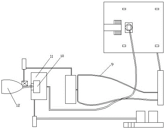
[0043] see figure 1 and figure 2 , a particle drilling method, comprising a particle injection step and a particle recovery step, the particle injection step refers to using an injection device to inject mud and particles into the well; the particle recovery step refers to the particles, cuttings and particles returned from the well The mud mixture relies on the fluid energy to flow directly to the recovery device through the outlet device at the wellhead of the drilling rig through the pipeline, and then the magnetic separator 10 in the recovery device sends the separated particles into the storage tank, and the cuttings and mud mixture are sent into the mud tank 11; the particles in the storage tank are transported to the injection device, injected into the well through the injection device and drilled again, forming a particle impact drilling cycle.

[0044] This embodiment is the most basic implementation mode, and the injection device and storage tank of the prior art c...

Embodiment 2

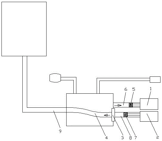
[0046] see Figure 1-Figure 3 , a particle drilling method, comprising a particle injection step and a particle recovery step, the particle injection step refers to using an injection device to inject mud and particles into the well; the particle recovery step refers to the particles, cuttings and particles returned from the well The mud mixture relies on the fluid energy to flow directly to the recovery device through the outlet device at the wellhead of the drilling rig through the pipeline, and then the magnetic separator 10 in the recovery device sends the separated particles into the storage tank, and the cuttings and mud mixture are sent into the mud tank 11; the particles in the storage tank are transported to the injection device, injected into the well through the injection device and drilled again, forming a particle impact drilling cycle.

[0047] The particle injection speed in the particle injection step is 0.5kg / s.

[0048] The particle injection pressure in the...

Embodiment 3

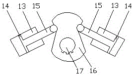
[0052] see figure 1 , image 3 and Figure 4 , a particle drilling method, comprising a particle injection step and a particle recovery step, the particle injection step refers to using an injection device to inject mud and particles into the well; the particle recovery step refers to the particles, cuttings and particles returned from the well The mud mixture relies on the fluid energy to flow directly to the recovery device through the outlet device at the wellhead of the drilling rig through the pipeline, and then the magnetic separator 10 in the recovery device sends the separated particles into the storage tank, and the cuttings and mud mixture are sent into the mud tank 11; the particles in the storage tank are transported to the injection device, injected into the well through the injection device and drilled again, forming a particle impact drilling cycle.

[0053] The particle injection speed in the particle injection step is 2kg / s.

[0054] The particle injection ...


PUM


Abstract

The invention discloses a particle drilling method, and belongs to the technical field of oil gas drilling engineering. The particle drilling method comprises steps of particle injection and particle recovery. The particle drilling method is characterized in that a. a slurry and particles are injected in a well through an injection device in the step of particle injection; b. a mixture of particles, rock debris and the slurry returned from the well is drained into a magnet separator after passing pipes from a rotary control head on a derrick floor in the step of particle recovery, and the magnet separator sends separated particles into a storage tank, and sends separated rock debris and slurry into a slurry tank; and c. particles in the storage tank are injected into the well again to drill through the injection device, to form a drilling cycle. According to the particle drilling method, the mixture of particles, rock debris and the slurry returned from the well is directly drained into a magnet separator through an exit device at the well head, particles can be separated and stored, a problem in the prior art that a slurry may leak from a plurality of positions because rock debris and the slurry are directly pumped into a drilling crew vibrating screen can be solved, and the risk of environmental pollution can be greatly reduced.

Description

technical field [0001] The invention relates to the technical field of oil and gas drilling engineering, in particular to a particle drilling method. Background technique [0002] The conventional drilling method is to use the drilling pressure and rotation of the drill bit at the bottom of the hole to mechanically break the rock to achieve the purpose of drilling. In this way, when encountering deep hard formations and strong abrasive formations, only the mechanical action of the drill bit is used to break the rocks. The function of the mud is only to carry cuttings, and it cannot achieve the combined rock breaking effect of hydraulic and mechanical, which has the problems of slow drilling speed, long cycle time and high cost. In recent years, particle impact drilling technology has been widely used as a revolutionary speed-increasing technology; particle impact drilling is a method of injecting spherical steel particles with a diameter of 1-3 mm into the bottom of the well...

Claims


Application Information

Patent Timeline
Patent Type & Authority Applications(China)
IPC IPC(8): E21B7/16
CPCE21B7/16
Inventor 李伟成姚建林陈晓彬陈立黄伟刘彬何超胡畔
Owner CCDC PETROLEUM CORING TECH
Why Eureka
Try Eureka