Method and device for driving a chain transmission and a chain clutch

A technology of chain transmission and equipment, applied in the direction of driving device, earth-moving drilling, propulsion, etc., can solve the problem of not providing sufficient protection and so on

Inactive Publication Date: 2018-03-06
MARCO SYSTEMANALYSE UND ENTWICKLUNG GMBH
View PDF5 Cites 0 Cited by
  • Summary
  • Abstract
  • Description
  • Claims
  • Application Information

AI Technical Summary

Problems solved by technology

Such elements do not provide adequate protection because they must apply the forces transmitted by the chain

Method used


Image

  • Method and device for driving a chain transmission and a chain clutch
  • Method and device for driving a chain transmission and a chain clutch
  • Method and device for driving a chain transmission and a chain clutch

Examples


Embodiment Construction

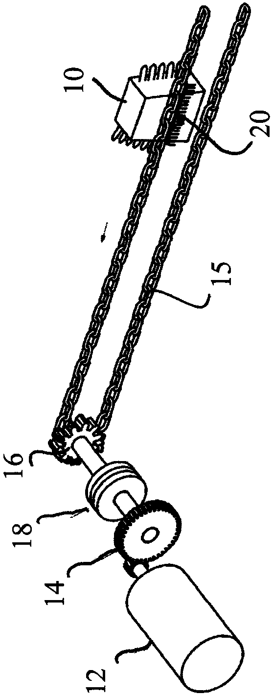
[0045] figure 1 An arrangement of a chain drive is shown, the driven component being the coal plow 10 in the exemplary embodiment shown. The chain drive shown is symmetrically constructed, wherein the second drive (with and figure 1 constructed in the same manner as shown in ) is not shown in the figure. exist figure 1 The illustrated chain drive comprises a drive motor which drives a sprocket 16 via a gearbox 14 , wherein a clutch 18 is arranged between the gearbox 14 and the sprocket 16 . A further clutch 20 is arranged in the region of the plow 10 . The clutch will be based on figure 2 with 3 will be described in detail, and unlike the clutch 18, this clutch is either fixed or not controllable.

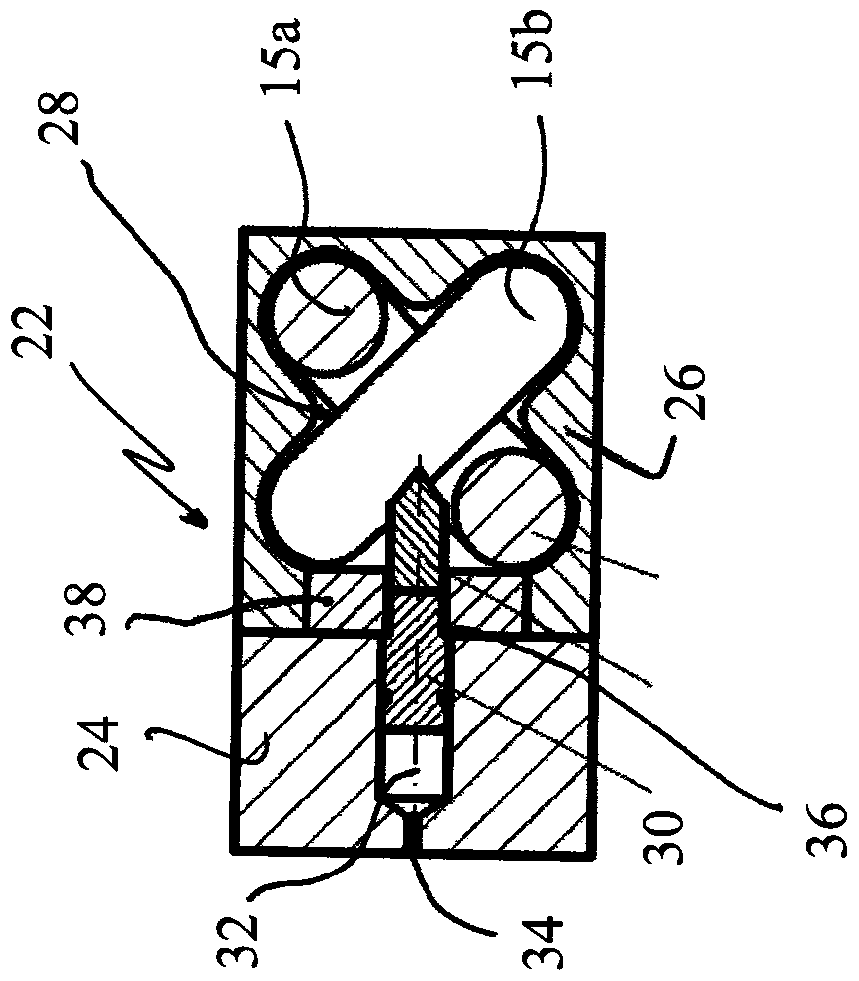
[0046] exist figure 2 with 3 The chain clutch arrangement shown in FIG. 2 includes a clutch housing 22 having a (interconnected) base part 24 and a guide part 26 , and both are fixed to the plow 10 . Here, the guide part 26 has a chain channel 28 , which has a substantia...


PUM


Abstract

The invention relates to a method and a device for driving a chain drive and a chain clutch. For the method for driving a chain drive, wherein an applicable clutch is provided between a drive motor and the chain driven by said drive motor, in order to transmit the desired torque from said drive motor to a sprocket , thereby appropriately selecting the torque transmittable through the clutch.

Description

[0001] This application is a divisional application of the application dated September 16, 2013, the application number is 201310421155.8, and the title of the invention is "method and equipment for driving chain transmission and chain clutch device". technical field [0002] The present invention relates to a method and apparatus for driving a chain drive, and a chain clutch for a chain drive in an underground mine. Background technique [0003] Such chain drives are known primarily for use in underground mines and, for example, for driving underground mining machines such as coal plows or drums and conveyor belts. Drives with frequency-controllable motors and high performance are used, for example, as drives for coal plows, wherein load balancing and smooth starting can be taken over by the motor. Of course, the chain (with which the mining machinery is moved back and forth) must be protected against dynamic overload. The overload is produced by the kinetic energy stored ...

Claims


Application Information

Patent Timeline
Patent Type & Authority Patents(China)
IPC IPC(8): E21C31/06
CPCE21C31/06E21C29/14E21C29/20
Inventor 马丁·路透
Owner MARCO SYSTEMANALYSE UND ENTWICKLUNG GMBH
Why Eureka
Try Eureka