Fluid centrifugal control system

A control system and fluid technology, applied in the direction of gas turbine devices, machines/engines, mechanical equipment, etc., can solve problems such as increased energy consumption, complex reliability, etc.

Inactive Publication Date: 2015-12-09
ZEROQ SCI & TECH
View PDF5 Cites 1 Cited by
  • Summary
  • Abstract
  • Description
  • Claims
  • Application Information

AI Technical Summary

Problems solved by technology

[0002] Object A performs rotational motion, and object B performs both rotational motion and revolution motion on the A object. In this case, a considerable rotational centrifugal force will be generated between the A object and the B object, thereby generating Considerable power consumption greatly increases the energy consumption of the system. The direction of action of this rotating centrifugal force is constantly changing in the geodetic coordinate system. The magnitude of the rotating centrifugal force also changes with the change of the speed of the A object. If the B The axis of rotation of the object is located on the centripetal direction of the A object, and a recessed area is set, and a pressurized fluid is introduced into the recessed area, and the pressure of the pressurized fluid can be used, and the pressure of the pressurized fluid can make the pressurized fluid The B object and the rotation axis of the B object are suspended in the centripetal direction of the A object, thereby greatly reducing the friction and power consumption generated by the rotating centrifugal force, but the pressure of the pressurized fluid will vary with the In order to achieve this change, the rotational speed can be sensed by a sensor, the size of the rotational centrifugal force can be calculated, and then the pressure of the pressurized fluid can be adjusted through an electromagnetic control valve or frequency conversion means. However, these processes very complex and unreliable

Method used


Image

  • Fluid centrifugal control system
  • Fluid centrifugal control system
  • Fluid centrifugal control system

Examples


Embodiment 1

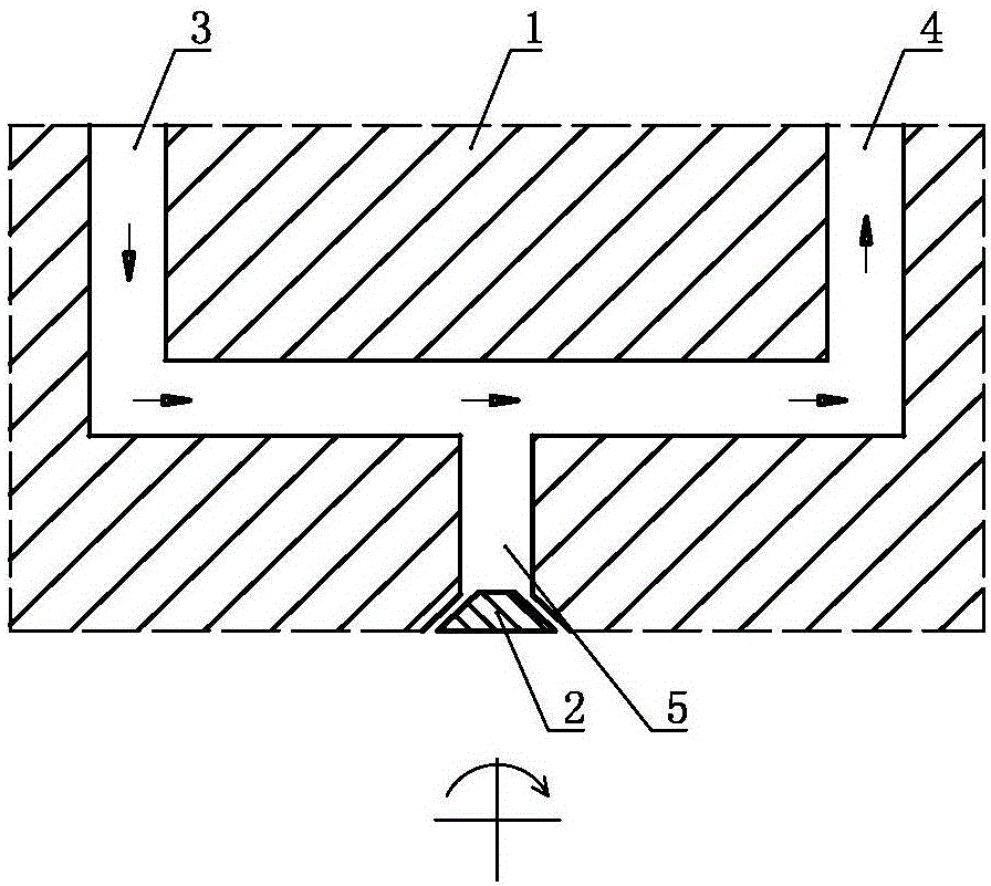
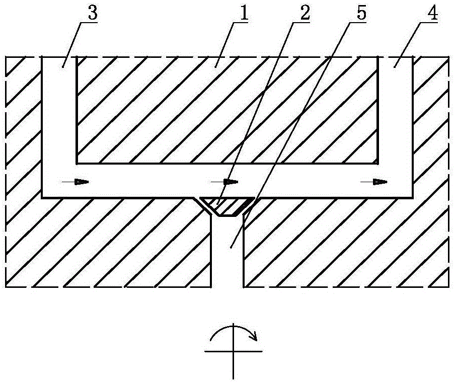
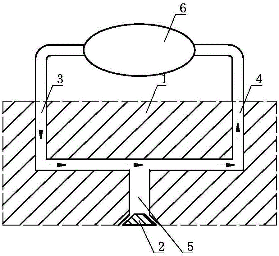
[0053] A fluid centrifugal control system, comprising a three-way fluid channel body 1 and a structure body 2, the three-way fluid channel body 1 includes an inflow channel 3, an outflow channel 4 and a discharge channel 5, the structure body 2 and the discharge channel The flow channels 5 are arranged correspondingly. The structure 2 is subjected to the joint action of the rotating centrifugal force and the fluid pressure in the inflow channel 3. The direction and effect of the fluid pressure in the inflow channel 3 acting on the structure 2 The angle between the acting directions of the rotating centrifugal force on the same structure 2 is greater than 90 degrees, and the displacement of the structure 2 controls the flow state of the discharge channel 5 .

Embodiment 2

[0055] A fluid centrifugal control system, such as figure 1 As shown, on the basis of Embodiment 1, the effect of the rotating centrifugal force further makes the structure 2 tend to close the discharge channel 5 .

Embodiment 3

[0057] A fluid centrifugal control system, such as figure 2 As shown, on the basis of Embodiment 1, the effect of the rotating centrifugal force further makes the structure 2 tend to open the discharge channel 5 .


PUM


Abstract

The invention discloses a fluid centrifugal control system. The system comprises a tee-joint fluid channel body and a structural body. The tee-joint fluid channel body comprises an inflow channel, an outflow channel and a discharging channel. The structural body corresponds to the discharging channel. Rotating centrifugal force and pressure of fluid in the inflow channel jointly act on the structural body. The included angle between the acting direction of the fluid, acting on the structural body, in the inflow channel and the acting direction of the rotating centrifugal force acting on the same structural body is larger than 90 degrees. The displacement of the structural body controls the circulating state of the discharging channel. The fluid centrifugal control system has the beneficial effects of being simple in structure, reliable in performance and the like.

Description

technical field [0001] The invention relates to the field of thermal energy and power, in particular to a fluid centrifugal control system. Background technique [0002] Object A performs rotational motion, and object B performs both rotational motion and revolution motion on the A object. In this case, a considerable rotational centrifugal force will be generated between the A object and the B object, thereby generating Considerable power consumption greatly increases the energy consumption of the system. The direction of action of this rotating centrifugal force is constantly changing in the geodetic coordinate system. The magnitude of the rotating centrifugal force also changes with the change of the speed of the A object. If the B The axis of rotation of the object is located on the centripetal direction of the A object, and a recessed area is set, and a pressurized fluid is introduced into the recessed area, and the pressure of the pressurized fluid can be used, and the...

Claims


Application Information

Patent Timeline
Patent Type & Authority Applications(China)
IPC IPC(8): F02C1/00
Inventor 靳北彪
Owner ZEROQ SCI & TECH
Why Eureka
Try Eureka