
Centrifugal fan

A technology of centrifugal fans and main boards, applied in non-variable pumps, non-displacement pumps, radial flow pumps, etc., can solve problems such as increased noise, reduced fan efficiency, and uneven airflow, so as to improve efficiency, Noise reduction effect

Inactive Publication Date: 2015-12-09
LG ELECTRONICS INC
View PDF8 Cites 3 Cited by
  • Summary
  • Abstract
  • Description
  • Claims
  • Application Information

AI Technical Summary

Problems solved by technology

In this process, in the prior art, eddy currents are formed due to the peeling of the flow that occurs at the respective outer peripheries of the protective cover and the main board, resulting in a problem that not only the efficiency of the fan is reduced, but also noise is generated.
[0004] In particular, the airflow sucked through the protective cover is pressurized by the blades and discharged while reaching the main plate along the direction of the rotation axis, so that there is a difference between the flow velocity in the above-mentioned upper region and the flow velocity in the above-mentioned lower region, causing the airflow to fail. Discharge evenly between the upper and lower areas, especially, the vortex generated by the deviation of the flow velocity between the upper and lower areas reduces the efficiency of the fan and increases the noise

Method used


Image

  • Centrifugal fan
  • Centrifugal fan
  • Centrifugal fan

Examples


Embodiment Construction

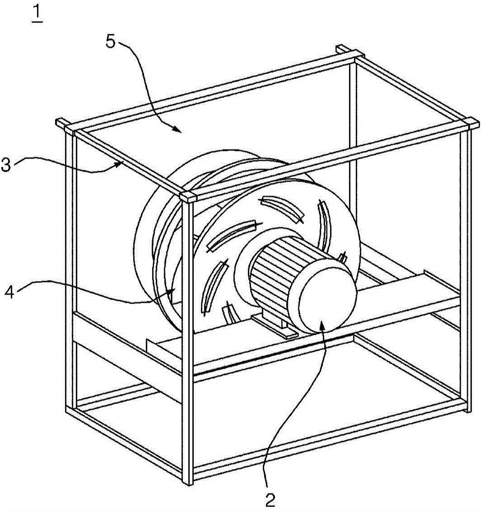
[0028] figure 1 A figure showing a plug-in fan module as an example of an applicable centrifugal fan. The centrifugal fans of the embodiments described below can be applied to refrigerators, air conditioners, vacuum cleaners, and the like. Since the air naturally flows into the inside of the fan and then is discharged outside, the above-mentioned centrifugal fan can be installed without a duct. Such as figure 1 The shown plug-in (plug) fan module 1 is suitable for an air conditioner, and the centrifugal fan in one embodiment of the present invention is suitable for a plug-in (plug) fan module 1. The air is cooled or heated and resupplied into the room.

[0029] The fan module 1 may include a motor 2 having a rotation shaft, a support frame 3 supporting the motor 2 , and a centrifugal fan 4 combined with the rotation shaft of the motor 2 . In addition, an opening through which air can flow into the centrifugal fan 4 is formed on the front panel 5 provided on the front surfa...


PUM


Abstract

Centrifugal fan including a main plate (110) rotating about an axis of rotation, a shroud (120) having an inlet port (121) for introduction of air, and a plurality of blades (130) circumferentially arranged between the main plate and the shroud so as to form a flow of air by accelerating air introduced through the inlet port, each having a pressure surface (131) formed such that a portion thereof (RC) near to the shroud is convex in a direction away from the axis of rotation and a portion thereof (CRC) near to the main plate is concave toward the axis of rotation, wherein the shroud has an inside surface formed as a curved surface, the curved surface has a diffusion section (DS) extending radially, the main plate has a curved surface (113) extending radially, and a curved surface of the shroud in the diffusion section at least partially overlaps with the curved surface formed in the main plate when viewed in a direction of the axis of rotation.

Description

technical field [0001] The present invention relates to centrifugal fans. Background technique [0002] A centrifugal fan is a fan that accelerates the air flowing in the axial direction through the protective cover, and discharges it in the radial direction (or centrifugal direction) between the blades. The performance of a centrifugal fan is affected not only by friction loss, impact loss, etc., but also by various shape factors. For example, the speed of the centrifugal fan, the shape of the blades, the main board or the protective cover, the angle or the number of the blades, etc. are representative factors affecting the performance of the centrifugal fan. [0003] In the centrifugal fan, air flows in through the suction port formed in the center of the protective cover, and after being accelerated by the blades, the air is discharged along the outer periphery of the protective cover at the upper area on the suction port side, and is discharged at the lower area far fro...

Claims


Application Information

Patent Timeline
IPC IPC(8): F04D29/44
CPCF04D29/601F04D17/10F04D29/281F04D29/288F04D29/30F04D29/403F04D29/666
Inventor 孙相陆郑春勉梁太万
Owner LG ELECTRONICS INC
Learn More