
Three-dimensional measuring system capable of reducing light reflection on surface of measured object

A technology for three-dimensional measurement and measured objects, applied in the direction of measuring devices, optical devices, instruments, etc., can solve problems such as uneven spraying, inapplicability, and impossible on-line detection occasions, to achieve accurate height values ​​and reduce excessive reflections Effect

Inactive Publication Date: 2015-12-09
东莞市盟拓智能科技有限公司
View PDF7 Cites 11 Cited by
  • Summary
  • Abstract
  • Description
  • Claims
  • Application Information

AI Technical Summary

Problems solved by technology

However, due to the possibility of uneven spraying during the painting process, in high-precision measurement occasions, even if the thickness of the spray paint is only 1-2 microns, this practice will have a significant impact on the measurement results
Moreover, in most cases, it is not allowed to spray paint on the surface of the measured object, and it is even more impossible for online detection.
This makes 3D measurement unsuitable for highly reflective objects to be measured. However, since the pins, pads, and gold wires of integrated circuits are metals in electronic devices, a large number of highly reflective objects require 3D measurement.

Method used


Image

  • Three-dimensional measuring system capable of reducing light reflection on surface of measured object
  • Three-dimensional measuring system capable of reducing light reflection on surface of measured object
  • Three-dimensional measuring system capable of reducing light reflection on surface of measured object

Examples


Embodiment Construction

[0032] In order to make the object, technical solution and advantages of the present invention clearer, the present invention will be further described in detail below in conjunction with the accompanying drawings and embodiments.

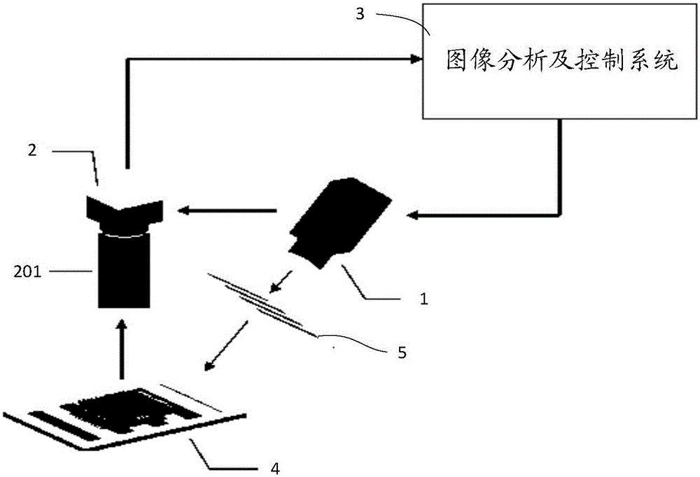
[0033] Such as figure 1 As shown, a three-dimensional measurement system of the present invention that can reduce reflection on the surface of the measured object includes an image analysis and control system 3 , a projector 1 and a camera 2 . The image analysis and control system 3 controls the projector 1 to generate structured light 5 , and the projector 1 projects the structured light 5 onto the surface of the object 4 to be measured from a first direction. After the structured light 5 is projected onto the surface of the measured object 4 , due to the unevenness of the surface of the measured object 4 , the structured light 5 will modulate the surface of the measured object 4 to form a deformed structured light pattern on the surface of the me...


PUM


Abstract

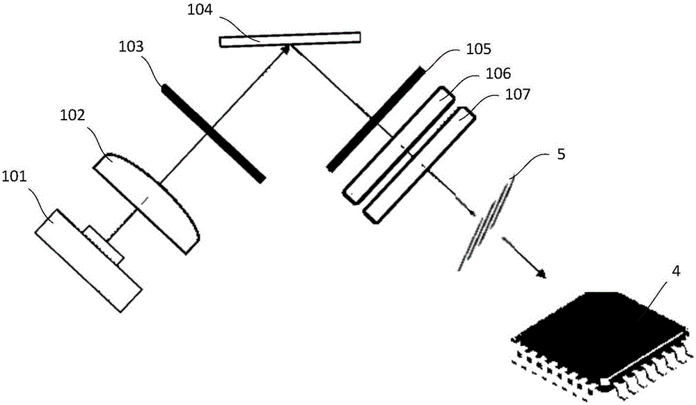
The invention relates to a tree-dimensional measuring system capable of reducing light reflection on the surface of a measured object. The system comprises an image analysis and control system, a projector, and a camera. The image analysis and control system is used to make the projector produce structured light. The projector is used to project the structured light from a first direction to the surface of a measured object so as to form a deformed structured light pattern on the surface of the measured object. The image analysis and control system is further used to acquire the deformed structured light pattern from a second direction through the camera and analyze the deformed structured light pattern in order to acquire depth information of the surface of the measured object. The system is characterized in that the projector includes a first circular polarizer; structured light passes through the first circular polarizer to form circularly-polarized structured light which is projected to the surface of a measured object; a second circular polarizer is mounted at the front end of the lens of the camera; the second circular polarizer is used to eliminate the non-circularly-polarized light portion in the light entering the camera; and the first circular polarizer and the second circular polarizer are left-handed circular polarizers or right-handed circular polarizers.

Description

technical field [0001] The invention relates to the technical field of three-dimensional measurement of object surfaces, in particular to a three-dimensional measurement system capable of reducing reflection on the surface of a measured object. Background technique [0002] In 3D measurement occasions, the measurement of shiny or highly reflective surfaces is a difficult problem. With the development of microfabrication and packaging technology, in surface inspection and quality control, the industry increasingly needs micron-level measurement of three-dimensional information, especially three-dimensional micro-measurement before and after surface mounting, before and after integrated circuit packaging, etc. . Micron-scale 3D micromeasurement is an enhancement of 2D measurement. However, there is still a lack of micron-scale three-dimensional measurement, both in terms of accuracy and economy. In fact, shiny or highly reflective objects pose a challenge to the measurement...

Claims


Application Information

Patent Timeline
Patent Type & Authority Applications(China)
IPC IPC(8): G01B11/24
Inventor 陈昌科
Owner 东莞市盟拓智能科技有限公司
Learn More