Microscope binocular stereo vision measurement device based on telecentric objectives

A technology of binocular stereo vision and telecentric objective lens, which is applied to measurement devices, optical devices, instruments, etc., can solve the problems of large lens distortion, large measurement error, small stereoscopic viewing angle, etc. The effect of improving precision and accuracy, reducing difficulty

Inactive Publication Date: 2015-12-09
HUAZHONG UNIV OF SCI & TECH
View PDF6 Cites 10 Cited by
  • Summary
  • Abstract
  • Description
  • Claims
  • Application Information

AI Technical Summary

Problems solved by technology

[0004] However, after further research, the above-mentioned prior art still has the following defects or deficiencies: since the digital microscope binocular stereo vision measurement is directly transformed from the binocular stereo microscope, the main body of the image acquisition unit remains unchanged, while the binocular stereo vision measurement is directly transformed from the binocular stereo microscope. In order to facilitate users to observe in a large range and depth, the microscope adopts a conventional zoom lens. At the same time, in order to meet the habit of a certain angle of view formed when people observe an object with binoculars, the stereoscopic angle of view of the left and right beams in the binocular tube is generally at 12 o ~15 o Therefore, the whole system has the problems of large lens distortion and small stereo viewing angle, and because the binocular tube of the binocular stereo microscope has been installed and fixed, it cannot be adjusted and the measurement error is large

Method used


Image

  • Microscope binocular stereo vision measurement device based on telecentric objectives
  • Microscope binocular stereo vision measurement device based on telecentric objectives
  • Microscope binocular stereo vision measurement device based on telecentric objectives

Examples


Embodiment Construction

[0021] In order to make the object, technical solution and advantages of the present invention clearer, the present invention will be further described in detail below in conjunction with the accompanying drawings and embodiments. It should be understood that the specific embodiments described here are only used to explain the present invention, not to limit the present invention. In addition, the technical features involved in the various embodiments of the present invention described below can be combined with each other as long as they do not constitute a conflict with each other.

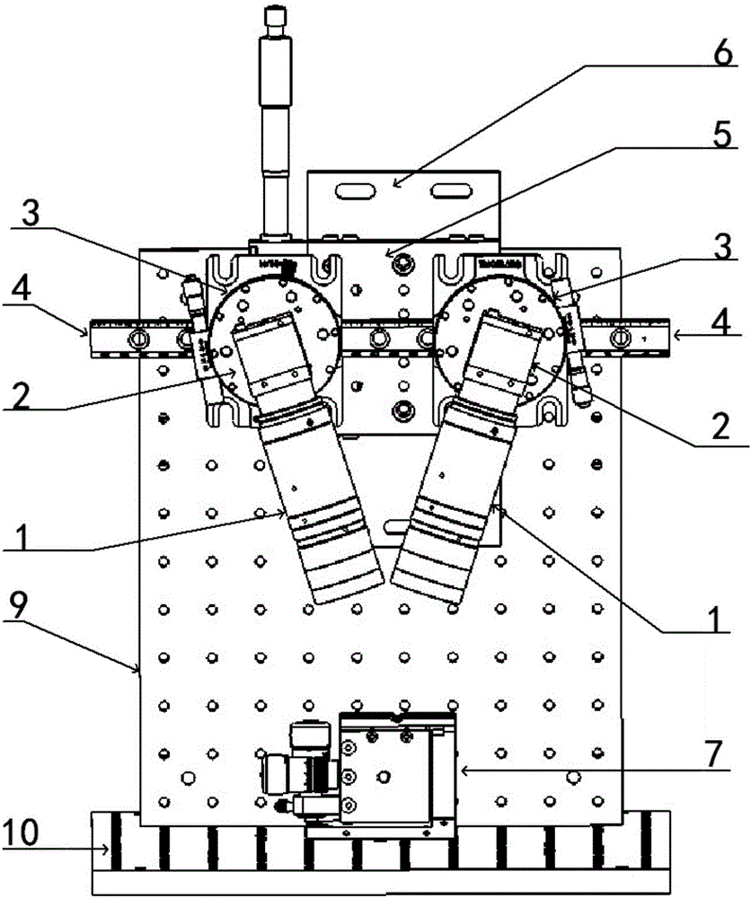
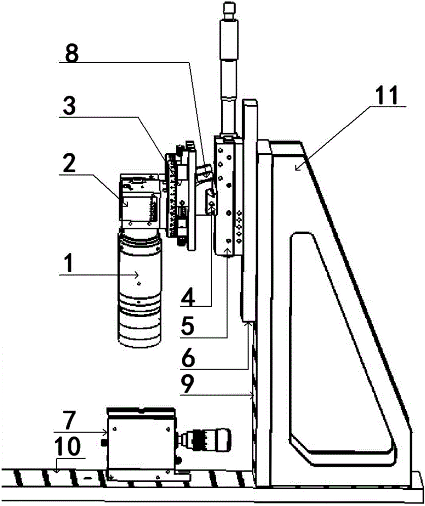
[0022] The basic principle of the present invention is that after the tiny sample block to be tested is evenly illuminated by a required light source, it is amplified by the telecentric objective lens, and focused and imaged on the light-receiving surface of the CCD image sensor. The received image is transmitted to the computer, and the computer obtains the three-dimensional size data of the mi...


PUM


Abstract

The invention discloses a microscope binocular stereo vision measurement device based on telecentric objectives. The device comprises a mounting fixing unit, a linear adjustment unit and image acquisition units. The mounting fixing unit comprises a support plate which is horizontally arranged and a mounting plate which is vertically arranged on the support plate. A three-axis displacement stage is arranged on the support plate. A tiny sample piece to be measured is placed on the three-axis displacement stage. The linear adjustment unit comprises a linear translation stage and a guide rail which is arranged on the linear translation stage. The linear translation stage is arranged on the mounting plate through a mounting bottom plate. Two image acquisition units are symmetrically arranged around the axis of the mounting plate. Each image acquisition unit comprises a telecentric objective, a CCD image sensor, a rotating platform and a slider. Each telecentric objective is connected with a CCD image sensor through a C interface. Each CCD image sensor is arranged on a rotating platform. Each rotating platform is arranged on the guide rail through a slider. The measurement device provided by the invention has the advantages of adjustable optical path angle, high measurement accuracy, good accuracy and the like.

Description

technical field [0001] The invention belongs to the field of microscopic stereo vision three-dimensional measurement devices, and more specifically relates to a microscopic binocular stereo vision measurement device based on a telecentric objective lens. Background technique [0002] As a non-contact measurement method, binocular stereo vision technology is widely used in the three-dimensional measurement of the conventional size of objects. At present, the 3D measurement system is mostly used in the binocular stereo vision 3D measurement of macroscopic objects, and the research on the binocular stereo vision 3D measurement of tiny objects is less, mainly due to the small size of tiny objects, it is difficult to observe them with traditional methods, and must Amplify with the help of equipment such as a microscope objective lens, but the field of view of the microscope objective lens is narrow and the depth of field is small, there is a conflicting relationship between the f...

Claims


Application Information

Patent Timeline
Patent Type & Authority Applications(China)
IPC IPC(8): G01B11/24
Inventor 史铁林陈科鹏廖广兰洪源张贻春王肖
Owner HUAZHONG UNIV OF SCI & TECH
Why Eureka
Try Eureka