
Method for preparing TEM chip sample

A chip and sample technology, which is applied in the field of preparing TEM chip samples, can solve problems such as easy oxidation, observation errors, and easy change of growth appearance, so as to prevent oxidation and corrosion and improve the success rate

Active Publication Date: 2015-12-09
SHANGHAI HUALI MICROELECTRONICS CORP
View PDF14 Cites 5 Cited by
  • Summary
  • Abstract
  • Description
  • Claims
  • Application Information

AI Technical Summary

Problems solved by technology

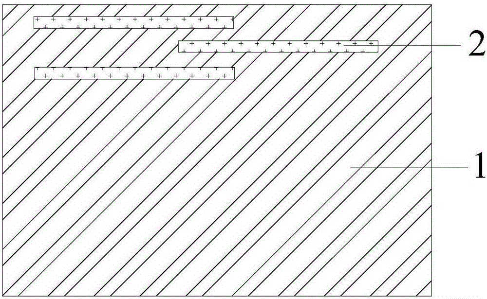
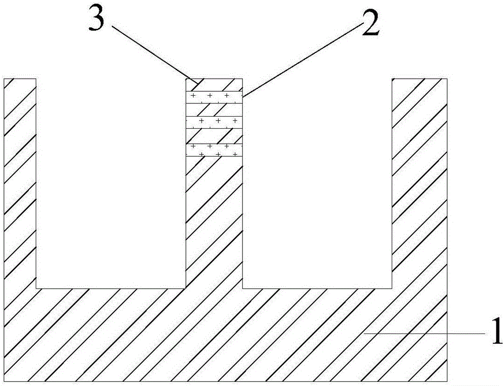
In the current chip manufacturing technology, the material of the metal circuit 2 that is subsequently grown is usually copper, and copper is easily oxidized when exposed to the air. Not only that, copper ions are easily diffused, causing the parts around the metal circuit 2 to be damaged to a certain extent. Therefore, the two sides of the sample sheet 3 are easy to change the original growth appearance, which makes the observation error

Method used


Image

  • Method for preparing TEM chip sample
  • Method for preparing TEM chip sample
  • Method for preparing TEM chip sample

Examples


Embodiment 1

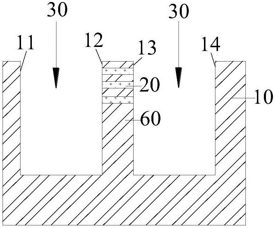
[0032] Please refer to Figure 6 , and combined with Figure 3 to Figure 5 , in order to achieve the above object, the present invention provides a kind of preparation TEM chip sample method, comprises the following steps:

[0033] Step 1: providing a chip 10 containing a metal circuit 20;

[0034] Step 2: Please refer to image 3 , use the focused ion beam 30 to cut the chip 10 containing the metal circuit 20, preferably, adjust the current intensity of the ion gun used to emit the focused ion beam 30 to 100pA~7000pA, use the focused ion beam 30 to cut the chip 10 in the middle part of the chip 10 Two grooves are cut out to expose the sample sheet 60 that needs to be observed in the middle. The inner walls of the two grooves form the first surface 11, the second surface 12, the third surface 13, and the fourth surface 14 in turn. These four The surfaces are parallel to each other, and metal circuits 20 are exposed on the second surface 12 and the third surface 13. Generall...


PUM


Abstract

The invention provides a method for preparing a TEM chip sample. The method includes the steps that a chip comprising a metal circuit is cut by a focused ion beam to form at least one surface exposing the metal circuit, and a carbon layer is deposited on the surface to cover the metal circuit. According to the method for preparing the TEM chip sample, the carbon layer is deposited on the surface exposing the metal circuit and used for protecting the metal circuit exposed out of the surface, in this way, the metal circuit will not make contact with outside air and is prevented from being oxidatively corroded by the outside air, even if the surface is covered with the carbon layer, sample observation in a TEM is not affected, and the success rate of sample preparation is increased.

Description

technical field [0001] The invention relates to the field of observing chip samples with a transmission electron microscope, in particular to a method for preparing TEM chip samples. Background technique [0002] Transmission Electron Microscope (TEM for short), referred to as TEM, is to project the accelerated and concentrated electron beam onto a very thin sample, and the electrons collide with the ions in the sample to change the direction, resulting in solid angle scattering, scattering angle The size of the sample is related to the density and thickness of the sample, so images with different light and shade can be formed, and the images will be displayed on imaging devices (such as fluorescent screens, films or photosensitive coupling components) after zooming in and focusing. Nowadays, transmission electron microscopy is widely and increasingly important in various fields including integrated circuit analysis, and FIB (Focused Ion Beam, Focused Ion Beam) sample prepar...

Claims


Application Information

Patent Timeline
IPC IPC(8): G01N1/28
Inventor 陈强
Owner SHANGHAI HUALI MICROELECTRONICS CORP
Learn More