Mechanical manufacturing drilling machine

A technology of mechanical manufacturing and drilling machines, which is applied in the field of mechanical manufacturing and drilling machines, can solve problems such as work errors, inconvenient operation, casualties, etc., and achieve the effects of reducing the probability of safety accidents, improving the fixation effect, and preventing injuries

Inactive Publication Date: 2019-12-03
蓝山县联佳合金铸造有限责任公司
View PDF0 Cites 3 Cited by
  • Summary
  • Abstract
  • Description
  • Claims
  • Application Information

AI Technical Summary

Problems solved by technology

[0002] Drilling machine refers to a machine tool that mainly uses a drill bit to process holes on a workpiece. Usually, the rotation of the drill bit is the main movement, and the axial movement of the drill bit is the feed movement. The drilling machine has a simple structure and relatively low machining accuracy. It can drill through holes, blind holes, and replace special tools. , can be expanded, countersink, reamed or tapped. During the processing, the workpiece does not move, let the tool move, align the center of the tool with the center of the hole, and rotate the tool. The characteristic of the drilling machine is that the workpiece is fixed and the tool Do rotary motion, but the mechanical manufacturing drilling machine currently used has the following defects: firstly, when the drill bit rotates, it is easy to cause waste material to splash and cause unnecessary casualties; Good and inconvenient to operate

Method used


Image

  • Mechanical manufacturing drilling machine
  • Mechanical manufacturing drilling machine
  • Mechanical manufacturing drilling machine

Examples


Embodiment Construction

[0018] The following will clearly and completely describe the technical solutions in the embodiments of the present invention with reference to the accompanying drawings in the embodiments of the present invention. Obviously, the described embodiments are only some, not all, embodiments of the present invention. Based on the embodiments of the present invention, all other embodiments obtained by persons of ordinary skill in the art without making creative efforts belong to the protection scope of the present invention.

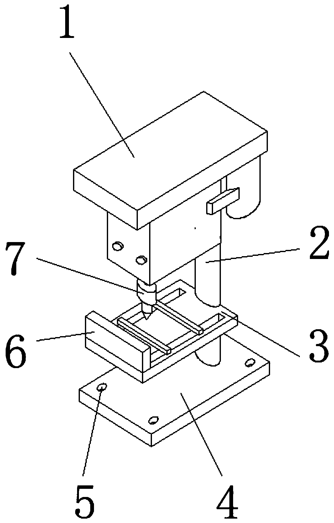
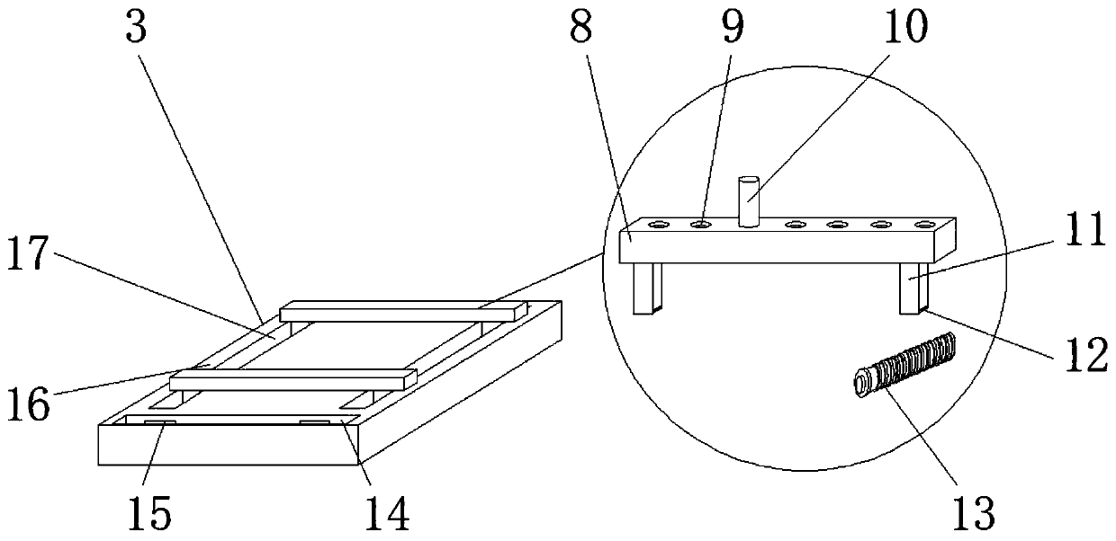
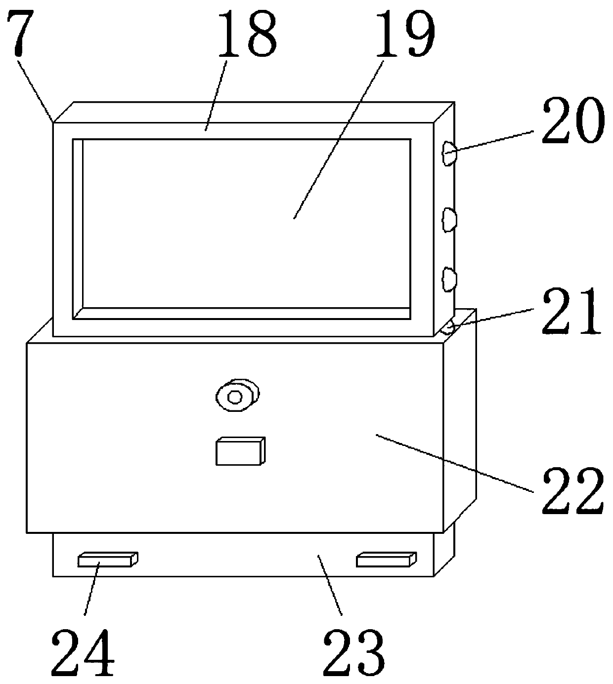
[0019] see Figure 1-3 , the present invention provides a technical solution: a machine-made drilling machine, comprising a fixed base 4, the four corners of the upper end surface of the fixed base 4 are fixedly provided with bolt holes 5, and the bolt holes 5 are distributed on the four corners of the upper end surface of the fixed base 4, using The device can be firmly fixed by using bolts through the bolt hole 5, the upper end surface of the fixed base 4 is...


PUM


Abstract

The invention discloses a machine manufacturing drilling machine with a fixed base; bolt holes are fixedly formed in the four corners of the upper end face of the fixed base. The upper end face of thefixed base is fixedly connected with a supporting column. A workpiece fixing device is fixedly connected to the middle of the side end face of the supporting column. The workpiece fixing device comprises a movable fixing plate, a threaded hole, a limiting column, a connecting column, a threaded clamping groove, a threaded column, a fixed clamping groove, piston clamping grooves, a fixed main bodyand a movable groove; the movable groove is formed in the upper end surface of the fixed main body; the movable fixing plate is slidably connected to the interior of the movable groove through the connecting column; the threaded hole is formed in the upper end face of the movable fixing plate, the limiting column is slidably connected to the upper end face of the movable fixing plate, the fixed clamping groove is formed in the side, away from the movable groove, of the upper end face of the fixed main body, and the piston clamping grooves are formed in the two sides of the interior of the fixed clamping groove. The drilling machine can provide good fixing performance for the workpiece, and meanwhile the safety performance of the device is greatly improved.

Description

[0001] The invention relates to the field of mechanical manufacturing, in particular to a drilling machine for mechanical manufacturing. Background technique [0002] Drilling machine refers to a machine tool that mainly uses a drill bit to process holes on a workpiece. Usually, the rotation of the drill bit is the main movement, and the axial movement of the drill bit is the feed movement. The drilling machine has a simple structure and relatively low machining accuracy. It can drill through holes, blind holes, and replace special tools. , can be expanded, countersink, reamed or tapped. During the processing, the workpiece does not move, let the tool move, align the center of the tool with the center of the hole, and rotate the tool. The characteristic of the drilling machine is that the workpiece is fixed and the tool Do rotary motion, but the mechanical manufacturing drilling machine currently used has the following defects: firstly, when the drill bit rotates, it is easy to...

Claims


Application Information

Patent Timeline
Patent Type & Authority Applications(China)
IPC IPC(8): B23B39/00B23Q3/06B23Q11/08
CPCB23B39/00B23Q3/06B23Q11/0825
Inventor 陈丽晖
Owner 蓝山县联佳合金铸造有限责任公司
Why Eureka
Try Eureka