Road underground cavity detection system and vehicle-mounted system

An underground cavity and detection system technology, applied in the field of data processing, can solve the problems that no technology can detect underground holes in roads, road safety, hidden dangers, etc., and achieve convenient and accurate positioning of problem point coordinates on the road surface, convenient post-processing, and convenient transmission channels Effect

Inactive Publication Date: 2015-12-09
朱荣华 +1
View PDF0 Cites 15 Cited by
  • Summary
  • Abstract
  • Description
  • Claims
  • Application Information

AI Technical Summary

Problems solved by technology

[0004] The purpose of the present invention is to provide a road underground cavity detection system and a vehicle-mounted system, aiming to solve the problem that there is no technology in the prior art that can detect the underground cavity in the road, which leads to the problem that many roads have potential safety hazards

Method used


Image

  • Road underground cavity detection system and vehicle-mounted system
  • Road underground cavity detection system and vehicle-mounted system
  • Road underground cavity detection system and vehicle-mounted system

Examples


Embodiment Construction

[0020] In order to make the object, technical solution and beneficial effects of the present invention more clear, the present invention will be further described in detail below in conjunction with the accompanying drawings and embodiments. It should be understood that the specific embodiments described here are only used to explain the present invention, not to limit the present invention.

[0021] In order to illustrate the technical solutions of the present invention, specific examples are used below to illustrate.

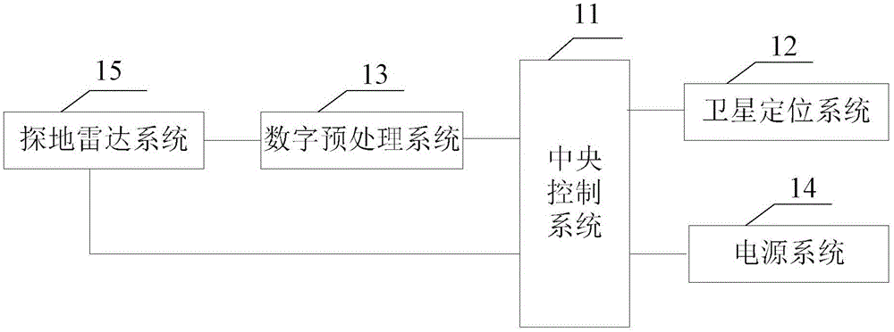
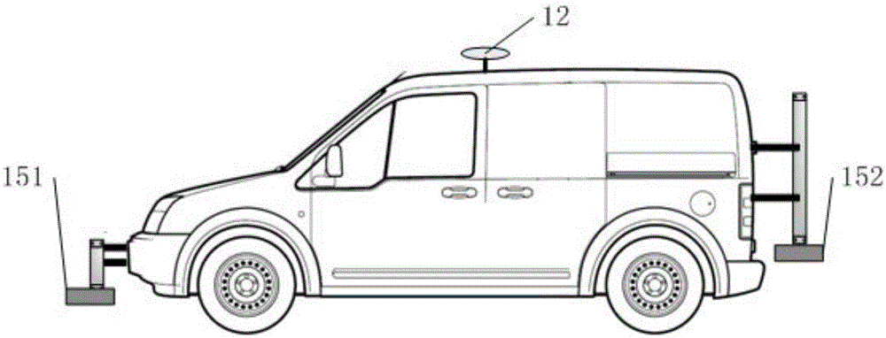
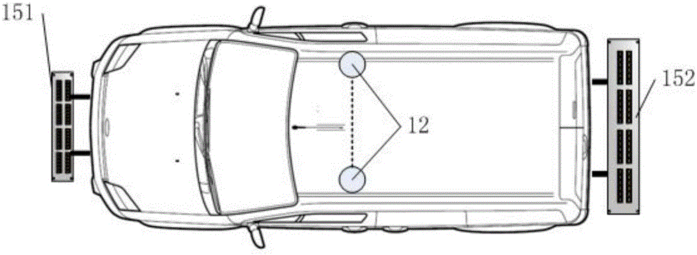
[0022] see figure 1 The road underground cavity detection system provided by Embodiment 1 of the present invention includes a central control system 11, a satellite positioning system 12 connected to the central control system 11, a digital preprocessing system 13, a power supply system 14, and a ground penetrating radar system 15. The processing system 13 is also connected to a ground penetrating radar system 15 . GPR system 15 may include surface-coupled G...


PUM


Abstract

The invention is applicable to the data processing field and provides a road underground cavity detection system and a vehicle-mounted system. The road underground cavity detection system comprises a central control system, a satellite positioning system, a digital pre-processing system, a power supply system and a ground penetrating radar system, wherein the satellite positioning system, the digital pre-processing system, the power supply system and the ground penetrating radar system are connected to the central control system, and the digital pre-processing system is connected to the ground penetrating radar system. The invention can detect the cavities under the road, restores the cavities underground in advance and thus prevents the collapse accidents.

Description

technical field [0001] The invention belongs to the field of data processing, and in particular relates to a road underground cavity detection system and a vehicle-mounted system. Background technique [0002] In recent years, underground cavity accidents on urban roads have occurred frequently. The formation of underground cavities is usually due to the local loosening and voiding of the soil layer after years of road use, and the gradual formation of underground cavities under the action of water erosion. With the improvement of urban road design standards, the structural layer of the road is getting thicker and stronger, and the local cavity under the structural layer is generally difficult to find. Only when the cavity has a certain scale and area, and under external force conditions such as vehicle rolling and rainwater immersion, will it collapse when it reaches a critical point. At this time, the cavity has expanded, and the collapse often causes more serious disaste...

Claims


Application Information

Patent Timeline
Patent Type & Authority Applications(China)
IPC IPC(8): G01V3/12
CPCG01V9/00H04L67/12H04W4/70
Inventor 朱荣华东君伟
Owner 朱荣华
Why Eureka
Try Eureka