Imaging lens, iris imaging module and binocular iris recognition device

An imaging lens and imaging module technology, applied in the field of biometrics, can solve the problems of complex operation, large volume, and high cost, and achieve the effect of good imaging quality, high imaging quality, and simple structure

Active Publication Date: 2015-12-09
BEIJING EYECOOL TECH CO LTD +1
View PDF5 Cites 13 Cited by
  • Summary
  • Abstract
  • Description
  • Claims
  • Application Information

AI Technical Summary

Problems solved by technology

[0003] At present, the optical imaging system of large-scale iris recognition devices generally adopts a zoom system, which is composed of more than a dozen lenses, and is equipped with complex motors and other mechanical structures to adjust the focus. The disadvantage is that it is large in size, complex in operation and high in cost, and can only be used in special occasions and fields; for the application of the general public, more convenient and miniaturized iris recognition equipment is needed, and its iris imaging optical system is usually a simple structure fixed Focusing system, the existing monocular acquisition optical system is mostly used, which is generally equipped with a lower pixel image sensor (VGA), its optical structure is simple, only 2-3 lenses are needed to achieve high imaging quality, but One eye requires a high degree of cooperation from the user, and the equipment can collect a very narrow range, which is extremely inconvenient to use and is not conducive to grasping the distance and alignment

Method used


Image

  • Imaging lens, iris imaging module and binocular iris recognition device
  • Imaging lens, iris imaging module and binocular iris recognition device
  • Imaging lens, iris imaging module and binocular iris recognition device

Examples


Embodiment 1

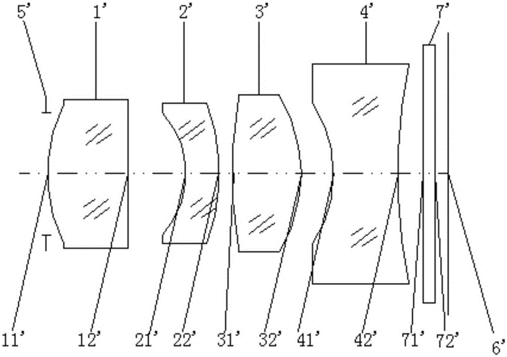
[0054] This embodiment is an imaging lens for binocular iris recognition, such as figure 2 As shown, it is composed of four lens groups, a diaphragm 5' and a flat filter 7'. An image sensor 6' is arranged behind the imaging lens. Along the optical axis, the order is: diaphragm 5', first lens 1' It is a concave-convex lens, its front surface 11' is convex, its rear surface 12' is concave, and has positive power; the second lens 2' is a concave-convex lens, its front surface 21' is concave, and its rear surface 22' is convex. It has negative refractive power; the third lens 3' is a biconvex lens, its front surface 31' is convex, and its rear surface 32' is convex, with positive refractive power; the fourth lens 4' is a biconcave lens, its front surface 41' is a concave surface, and the rear surface 42' is a concave surface with negative power; the plane filter 7' is located between the fourth lens and the imaging surface, and the imaging surface is the image sensor surface, usi...

Embodiment 2

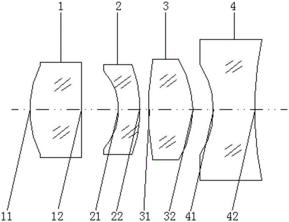
[0062] This embodiment is an imaging lens for binocular iris recognition, such as Figure 4 As shown, it consists of four lens groups and a diaphragm 5", and an image sensor 6" is arranged at the rear of the imaging lens. The surface 12" is a concave surface with positive refractive power; the stop is 5", the second lens 2" is a concave-convex lens, the front surface 21" is concave, and the rear surface 22" is convex and has negative refractive power; Three lens 3 " is biconvex lens, and its front surface 31 " is convex, and back surface 32 " is convex, has positive optical power; The fourth lens 4 " is biconcave lens, and its front surface 41 " is concave, and back surface 42 "is a concave surface with negative refractive power; the diaphragm 5" is located between the first lens and the second lens, and the imaging surface is the image sensor surface, using a CCD or Cmos sensor. The four lenses are all even-order aspherical lenses made of plastic. The imaging wavelength of ...


PUM


Abstract

The invention discloses an imaging lens, an iris imaging module and a binocular iris recognition device. The imaging lens, an iris imaging module and a binocular iris recognition device belong to the field of biological recognition. The imaging lens successively comprises the following components in an optical axis direction from front to back: a first lens which is a convexoconcave lens with a positive focal power, wherein the front surface of the first lens is a convex surface and the back surface of the first lens is a recessed surface; a second lens which is convexoconcave lens with a negative focal power, wherein the front surface of the second lens is a recessed surface and the back surface of the second lens is a convex surface; a third lens which is a biconvex lens with a positive focal power, wherein the front surface and the back surface of the third lens are convex surfaces; and a fourth lens which is a biconcave lens with a negative focal power, wherein the front surface and the back surface of the fourth lens are recessed surfaces. The front surface and/or the back surface of each of the first lens, the second lens, the third lens and the fourth lens are aspheric. The imaging lens has advantages of simple structure, small size, high imaging quality and small distortion. The imaging lens is suitable for binocular iris acquisition.

Description

technical field [0001] The invention relates to the field of biological identification, in particular to an imaging lens, an iris imaging module and a binocular iris identification device. Background technique [0002] With the advent of the Internet information age, people's requirements for the security and stability of information, especially personal information, have been continuously improved, and the application of identity authentication by using people's inherent unique physiological or behavioral characteristics has become more and more extensive. Among them, iris recognition technology As the "most accurate" and "hardest to counterfeit" biometric technology is increasingly favored by everyone. However, iris recognition is a biometric technology based on the texture characteristics of the iris of the eye. Since the surface of the iris is spherical, the area is small, and the color is dark, the imaging quality of the optical system for collecting iris images is high...

Claims


Application Information

Patent Timeline
Patent Type & Authority Applications(China)
IPC IPC(8): G02B13/18G02B13/00G06K9/00
Inventor 马淑媛
Owner BEIJING EYECOOL TECH CO LTD
Why Eureka
Try Eureka