Color film substrate, display panel and preparation method thereof, and display device

A color filter substrate and display panel technology, which is applied in the direction of instruments, nonlinear optics, optics, etc., can solve the problems of color filter substrate and array substrate bending offset, lower transmittance, product cost and power consumption increase, etc.

Active Publication Date: 2015-12-09
BOE TECH GRP CO LTD +1
View PDF6 Cites 13 Cited by
  • Summary
  • Abstract
  • Description
  • Claims
  • Application Information

AI Technical Summary

Problems solved by technology

However, in the production of curved liquid crystal display panels, the biggest problem is that the color filter substrate and the array substrate are offset when they are bent, which will cause the black matrix to be unable to completely cover the transmitted light, resulting in a decrease in picture qu

Method used


Image

  • Color film substrate, display panel and preparation method thereof, and display device
  • Color film substrate, display panel and preparation method thereof, and display device
  • Color film substrate, display panel and preparation method thereof, and display device

Examples


Embodiment 1

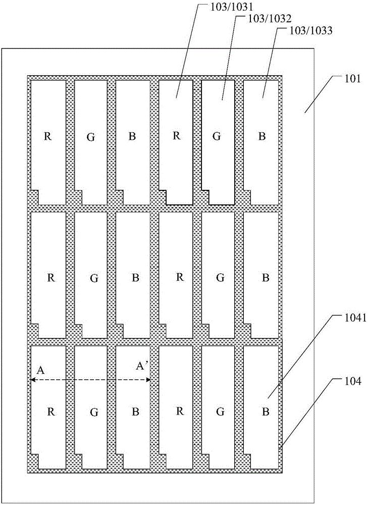
[0053] This embodiment provides a color filter substrate. Such as Figure 1a As shown, the color filter substrate includes a base substrate 101 and a color filter layer 102 and a phase inversion pattern 104 disposed on the base substrate 101 . The color filter layer 102 includes a plurality of filter units 103 . For example, the filter unit 103 may include a red filter unit 1031 , a green filter unit 1032 and a blue filter unit 1033 . For example, a plurality of filter units 103 are arranged on the base substrate 101 in an array. It should be noted that the color filter layer 102 includes but is not limited to the red, green and blue filter units described in this embodiment, and may also include filter units of other colors.

[0054] Such as Figure 1a As shown, the phase inversion pattern 104 includes a plurality of openings 1041, and the plurality of openings 1041 correspond to a plurality of filter units 103 of the color filter layer. For example, one opening 1041 corres...

Embodiment 2

[0068] This embodiment provides a display panel, such as Figure 9 As shown, it includes the array substrate 110 and any color filter substrate described in Embodiment 1.

[0069] For example, in an example of this embodiment, the array substrate 110 may include a plurality of first signal lines 111 and a plurality of second signal lines 118, and the intersections of the plurality of first signal lines 111 and the plurality of second signal lines 118 define a plurality of Pixel unit 112 . For example, the first signal line 111 is a vertical data line, and the second signal line 118 is a horizontal gate line. A plurality of gate lines and a plurality of data lines intersect to define a plurality of sub-pixel units 112 . The sub-pixel unit 112 corresponds to the filter unit 103 of the color filter substrate. For example, the plurality of sub-pixel units 112 defined by the intersections of the plurality of first signal lines 111 and the plurality of second signal lines 118 are...

Embodiment 3

[0080] This embodiment provides a display panel. Such as Figure 13a As shown, the display panel includes a liquid crystal cell 200 , the array substrate 110 and the color filter substrate 100 are disposed opposite to form the liquid crystal cell 200 , and the liquid crystal cell 200 also includes a liquid crystal layer 120 disposed between the color filter substrate 100 and the array substrate 110 .

[0081] The polarizer 106 is disposed on the surface of the packaged color filter substrate away from the array substrate, and the phase inversion pattern 104 is disposed on the surface of the polarizer 106 away from the color filter substrate 100 . The phase inversion pattern 104 provided on the surface of the polarizer 106 away from the color filter substrate 100 can be as follows Figure 13b shown.

[0082] The difference between this embodiment and the display panels provided by the above-mentioned embodiments is that the phase inversion pattern 104 is not arranged on the b...


PUM


Abstract

The invention discloses a color film substrate, a display panel and a display device. The color film substrate comprises a base substrate, a colored filter layer and a phase reversal pattern, wherein the colored filter layer and the phase reversal pattern are arranged on the base substrate, the phase reversal pattern comprises multiple openings, the multiple openings correspond to multiple filter units of the colored filter layer, and the phase reversal pattern is used for defining the boundary of each filter unit; the projection of the phase reversal pattern on the base substrate is at least partially covered on the projection of an area between adjacent filter units on the base substrate; and the phase reversal pattern is configured for enabling light passing through the phase reversal pattern to generate phase reversal. The color film substrate can replace or partly replace a black matrix by forming the phase reversal pattern on the base substrate, and due to the adoption of the color film substrate, the generation of light leak caused by bending, of the display panel, can be prevented.

Description

technical field [0001] At least one embodiment of the present invention relates to a color filter substrate, a display panel, a manufacturing method thereof, and a display device. Background technique [0002] With the development of display technology, liquid crystal display panels are widely used in various display devices, such as mobile phones, watches, computers, tablet computers, and televisions. The basic structure of the liquid crystal display panel includes an array substrate (Array Substrate) and a color filter substrate (ColorFilter Substrate), and a liquid crystal (Liquid Crystal) layer sandwiched between the two substrates. In the liquid crystal display panel, the black matrix (BlackMatrix, BM) is a very important component, and its basic function is to shield light, avoid light leakage and color mixing between sub-pixels, so as to achieve the purpose of improving contrast and reducing external light reflection. [0003] On the other hand, with the pursuit of h...

Claims


Application Information

Patent Timeline
IPC IPC(8): G02F1/1335G02F1/1333
CPCG02F1/1333G02F1/133512G02F1/133514G02F1/133528G02F1/133531G02F1/133638G02F1/133516G02F1/136286G02F2201/52G02F2201/56
Inventor 江鹏江亮亮贾纬华杨海鹏金在光尹傛俊
Owner BOE TECH GRP CO LTD
Why Eureka
Try Eureka