

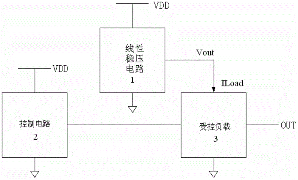
System improving load regulation rate of low-pressure-difference linear voltage regulator
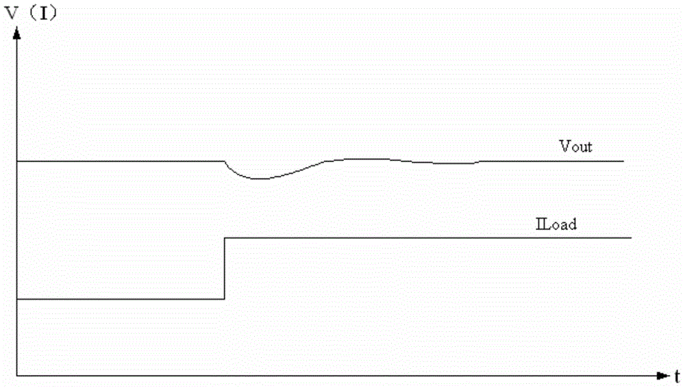
A technology of load regulation and low dropout linearity, which is applied in the electronic field, can solve the problems that affect the stable operation of the system and the large fluctuation of output voltage, so as to ensure the stability of the system and improve the effect of load regulation
- Summary
- Abstract
- Description
- Claims
- Application Information
AI Technical Summary
Problems solved by technology
Method used
Image

Examples
Embodiment Construction
[0026] The technical solutions in the embodiments of the present invention will be clearly and completely described below in conjunction with the accompanying drawings in the embodiments of the present invention. Obviously, the described embodiments are only a part of the embodiments of the present invention, rather than all the embodiments. Based on the embodiments of the present invention, all other embodiments obtained by those of ordinary skill in the art without creative work shall fall within the protection scope of the present invention.
[0027] It should be noted that the embodiments of the present invention and the features in the embodiments can be combined with each other if there is no conflict.
[0028] The present invention will be further described below with reference to the drawings and specific embodiments, but it is not a limitation of the present invention.
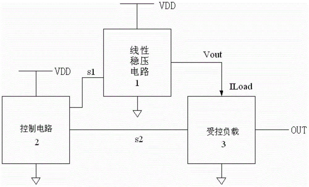
[0029] Reference image 3 , Figure 4 , A system for improving the load regulation rate of a low-dropout ...
PUM
 Abstract
Description
Claims
Application Information