Blind element compensation method for infrared or terahertz image

A blind element compensation and terahertz technology, applied in the field of uncooled infrared detection, can solve the problems of large error, blurred details, loss of image details, etc., and achieve the effect of small error, good edge information and detail information, and clear image quality

Inactive Publication Date: 2015-12-09
UNIV OF ELECTRONICS SCI & TECH OF CHINA
View PDF1 Cites 5 Cited by
  • Summary
  • Abstract
  • Description
  • Claims
  • Application Information

AI Technical Summary

Problems solved by technology

The first two methods are simple in process, strong in operability, and suitable for real-time processing, but the disadvantage is that the error is too large, and some details of the image are lost, making the details partially blurred

Method used


Image

  • Blind element compensation method for infrared or terahertz image
  • Blind element compensation method for infrared or terahertz image
  • Blind element compensation method for infrared or terahertz image

Examples


Embodiment Construction

[0023] The specific steps of the blind element compensation method for an infrared or terahertz image according to an embodiment of the present invention will be described in detail below with reference to the accompanying drawings.

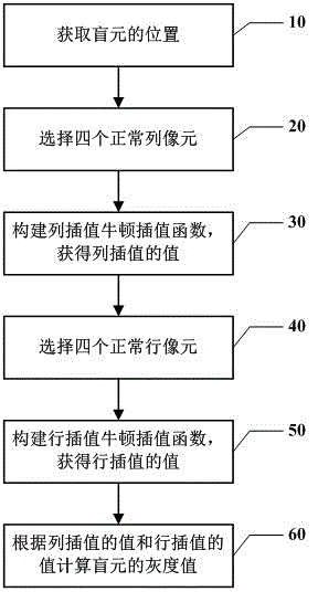
[0024] figure 1 It is a schematic flowchart of a blind element compensation method for an infrared or terahertz image according to an embodiment of the present invention.

[0025] Such as figure 1 As shown, in step 10, the position of the blind pixel in the infrared or terahertz image is first obtained. For example, get the row and column where the blind pixel is located in the infrared or terahertz image.

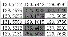
[0026] For example, for an infrared or terahertz image with a size of M×N, M represents the number of rows of the infrared or terahertz image, and N represents the number of columns of the infrared or terahertz image. Let I(i, j) represent the gray value of each pixel point in the infrared or terahertz image, i=1,...,M, j=1,...,N. For exa...


PUM


Abstract

An embodiment of the invention discloses a blind element compensation method for an infrared or terahertz image. The blind element compensation method comprises the steps of selecting X normal row image elements in a row on which the blind element is arranged; constructing a Newton interpolation function according to the X normal row image elements and calculating a row interpolation value of the blind element; selecting X normal line image elements from a line on which the blind element is arranged; constructing a Newton interpolation function according to the X normal line image elements and calculating a line interpolation value of the blind element; and calculating the gray level of the blind element according to the row interpolation value and the line interpolation value. The gray level which is compensated according to the blind element compensation method provided by the embodiment of the invention further approaches a real value and has a smaller error. Furthermore the blind element compensation method can better keep the edge information and the detail information of a target image and furthermore has higher image quality.

Description

technical field [0001] The invention relates to the technical field of uncooled infrared detection, in particular to a blind element compensation method for infrared or terahertz images. Background technique [0002] At present, with the continuous improvement of semiconductor manufacturing technology and the continuous improvement of application requirements, infrared focal plane detection technology has developed rapidly and has been widely used in military and civilian fields. The infrared focal plane array (InfraredFocalPlaneArray, IRFPA) as the core of the infrared detection system, its performance determines the quality of the infrared imaging system. [0003] However, affected by factors such as detector manufacturing process and materials, blind element phenomenon will inevitably appear in the infrared focal plane array. The existence of blind pixels will reduce the signal-to-noise ratio and image quality of infrared or terahertz images. Blind pixel defect refers...

Claims


Application Information

Patent Timeline
Patent Type & Authority Applications(China)
IPC IPC(8): G06T5/00
Inventor 刘子骥刘玉林范俊陈伟钦郑兴蒋亚东
Owner UNIV OF ELECTRONICS SCI & TECH OF CHINA
Why Eureka
Try Eureka