
Preparation method of array substrate, array substrate, display panel and display device

A technology for array substrates and display panels, applied in semiconductor/solid-state device manufacturing, electrical components, electric solid-state devices, etc., can solve the problems of complex process and high cost, achieve cost reduction, reduce requirements, control precision, and save patterning process Effect

Inactive Publication Date: 2015-12-09
BOE TECH GRP CO LTD +1
View PDF7 Cites 3 Cited by
  • Summary
  • Abstract
  • Description
  • Claims
  • Application Information

AI Technical Summary

Problems solved by technology

[0006] The purpose of the present invention is to solve the problems in the prior art that the light-shielding layer and the active layer of the array substrate are patterned separately and the production process is complex and the cost is high.

Method used


Image

  • Preparation method of array substrate, array substrate, display panel and display device
  • Preparation method of array substrate, array substrate, display panel and display device
  • Preparation method of array substrate, array substrate, display panel and display device

Examples


Embodiment 1

[0040] Such as figure 1 As shown, this embodiment provides a method for preparing an array substrate, including the following steps:

[0041] A step of forming patterns of an amorphous silicon layer and a polysilicon layer arranged at intervals by using the same mask plate.

[0042] In the preparation method of the array substrate in this embodiment, since the light-shielding layer and the active layer of the array substrate are patterned by using the same mask, the number of masks is saved, the one-step patterning process is saved, and the cost is reduced; At the same time, there is no need to consider the alignment problem in the patterning process, which reduces the requirements for equipment and control accuracy.

[0043] Specifically, the following steps can be used to prepare the array substrate:

[0044] S1: a step of sequentially depositing a first buffer layer, a first amorphous silicon layer, a second buffer layer, and a second amorphous silicon layer on the substr...

Embodiment 2

[0059] This embodiment provides another method for preparing an array substrate. Specifically, the following steps can be used to prepare the array substrate:

[0060] S1: a step of sequentially depositing a first buffer layer, a first amorphous silicon layer, a second buffer layer, and a second amorphous silicon layer on the substrate;

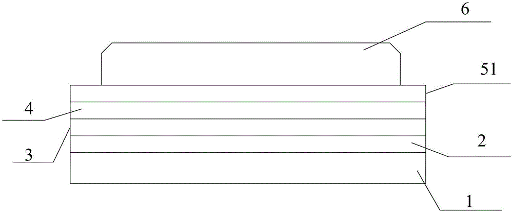
[0061] Such as figure 1As shown, a first buffer layer 2, a first amorphous silicon layer 3, a second buffer layer 4, and a second amorphous silicon layer 5 are sequentially deposited on a substrate 1,

[0062] It should be understood that the above-mentioned functional layer can be prepared by plasma-enhanced chemical vapor deposition, and the specific deposition method is within the scope of the prior art, and will not be repeated here.

[0063] S2: a step of converting the second amorphous silicon layer into a polysilicon layer;

[0064] Such as figure 2 As shown, the second amorphous silicon layer 5 is subjected to dehydrogenation trea...

Embodiment 3

[0071] This embodiment provides an array substrate, which is prepared by using the above-mentioned method for preparing an array substrate.


PUM


Abstract

The invention provides a preparation method of an array substrate, the array substrate, a display panel and a display device, belongs to the technical field of display, and can solve problems of complex technology and relatively high cost due to respective patterning of a light blocking layer and an active layer of the array substrate in the prior art. According to the preparation method of the array substrate, the array substrate, the display panel and the display device, the light blocking layer and the active layer of the array substrate are patterned by adopting the same mask plate so that the number of the mask plate is saved, one step of patterning technology is saved and cost is reduced. Meanwhile, an alignment problem in the process of the patterning technology does not need to be considered so that the equipment requirement and control precision can be reduced.

Description

technical field [0001] The invention belongs to the field of display technology, and in particular relates to a method for preparing an array substrate, an array substrate, a display panel, and a display device. Background technique [0002] Array substrates in display devices generally include thin-film transistors formed of polysilicon as the active layer. High-energy light from the backlight or ambient light irradiates the channel region of the polysilicon active layer, which will cause electronic transitions and other phenomena, thereby affecting the thin-film transistor. stability. [0003] Generally, a light-blocking layer is set between the backlight or ambient light and the active layer. In order to protect the channel area of ​​the active layer to the greatest extent, the size of the light-blocking layer is generally designed to be greater than or equal to the active layer. The size of the light-blocking layer and the active layer are aligned in the incident direct...

Claims


Application Information

Patent Timeline
Patent Type & Authority Applications(China)
IPC IPC(8): H01L21/77H01L27/12
CPCH01L27/1288H01L27/1214
Inventor 赵生伟刘华锋张凯
Owner BOE TECH GRP CO LTD
Learn More