A video wall system and its realization method

An implementation method and splicing wall technology, which are applied to CCTV systems, components of TV systems, TVs, etc., can solve the problems that the display end of the splicing wall does not have the matrix function and echo function, and are inconvenient to use, so as to overcome the loss of frames. and delay, reducing the cost of installation

Active Publication Date: 2019-09-10
SHENZHEN HUASHENG SOFTWARE TECH CO LTD +1
View PDF5 Cites 0 Cited by
  • Summary
  • Abstract
  • Description
  • Claims
  • Application Information

AI Technical Summary

Problems solved by technology

[0004] In view of the deficiencies in the prior art above, the purpose of the present invention is to provide users with a splicing wall device and its implementation method, which overcomes the fact that the display end of the splicing wall itself does not have a matrix function and an echo function in the prior art, resulting in When performing video splicing and display, the matrix module and the signal distributor module must be configured separately, resulting in the disadvantage of inconvenient use

Method used


Image

  • A video wall system and its realization method
  • A video wall system and its realization method
  • A video wall system and its realization method

Examples


Embodiment Construction

[0031] In order to make the object, technical solution and advantages of the present invention more clear and definite, the present invention will be further described in detail below with reference to the accompanying drawings and examples. It should be understood that the specific embodiments described here are only used to explain the present invention, not to limit the present invention.

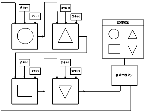
[0032] The present invention provides a video wall system, such as figure 1 As shown, the splicing wall system includes: at least two connected splicing units and a monitoring device connected to the front and rear ends of the connected splicing units, and connected to the connected splicing units and integrated inside the monitoring device Or a signal control unit set independently from the monitoring device; figure 1 Take the 2x2 splicing wall as an example, which contains 4 splicing units. If there are multiple splicing units, use the same as figure 1 The connection method shown con...


PUM


Abstract

The invention provides a spliced screen system and an implementation method thereof. An inner-loop signal processing chip for converting a specified local audio / video signal received by a local video signal interface into a DP signal is arranged in each splicing unit. On one hand, the DP signal output by the inner-loop signal processing chip is converted into an LVDS signal, and on the other hand, the DP signal is output to a core processing chip of a next splicing unit which is connected with a DP output interface through the DP output interface, so that an internal matrix function of a spliced screen and an echo function of playing back a whole spliced screen display image onto a monitor of a remote control end in real time are realized. Additional separate configuration of a matrix module and a signal distributor module for the spliced screen is not required; convenience is brought to remote control of the spliced screen; the installation cost is lowered; and the defects of frame loss and delay of transmitted signals are overcome.

Description

technical field [0001] The invention relates to the field of public service equipment, in particular to a splicing wall system and an implementation method thereof. Background technique [0002] In the existing traditional splicing wall device, the display terminal of the splicing wall only plays the role of display. It needs to configure a matrix module and a signal distributor module separately on the periphery to put multiple signals to each display terminal of the splicing wall. display; moreover, when the video, image and roaming interface are displayed on the splicing wall, the conventional splicing device cannot display the picture and content of the current splicing wall in real time on the remote monitoring end, which affects the convenience of interactive control and monitoring at the remote control end ; However, devices using network codecs have the disadvantages of high price, image compression, frame loss, delay, and low bandwidth. [0003] Therefore, prior ar...

Claims


Application Information

Patent Timeline
Patent Type & Authority Patents(China)
IPC IPC(8): H04N7/18H04N5/262
Inventor 范国仁秦海华李卫刚郗宏涛郭春亮
Owner SHENZHEN HUASHENG SOFTWARE TECH CO LTD
Why Eureka
Try Eureka