Suction-type cleaner with dedusting control for the filter or the filters

A technology for cleaning positions and vacuum cleaners. It is applied to devices for cleaning filters, vacuum cleaners, cleaning equipment, etc. It can solve the problem of consuming extra force and achieve the effects of small driving power, reliable jitter, and small current demand.

Active Publication Date: 2015-12-09
NILFISK
View PDF10 Cites 5 Cited by
  • Summary
  • Abstract
  • Description
  • Claims
  • Application Information

AI Technical Summary

Problems solved by technology

[0010] Here too, there is the disadvantage that the drive motor for actuating the valve rod has to expend additional force due to the action of the suction press

Method used


Image

  • Suction-type cleaner with dedusting control for the filter or the filters
  • Suction-type cleaner with dedusting control for the filter or the filters
  • Suction-type cleaner with dedusting control for the filter or the filters

Examples


Embodiment Construction

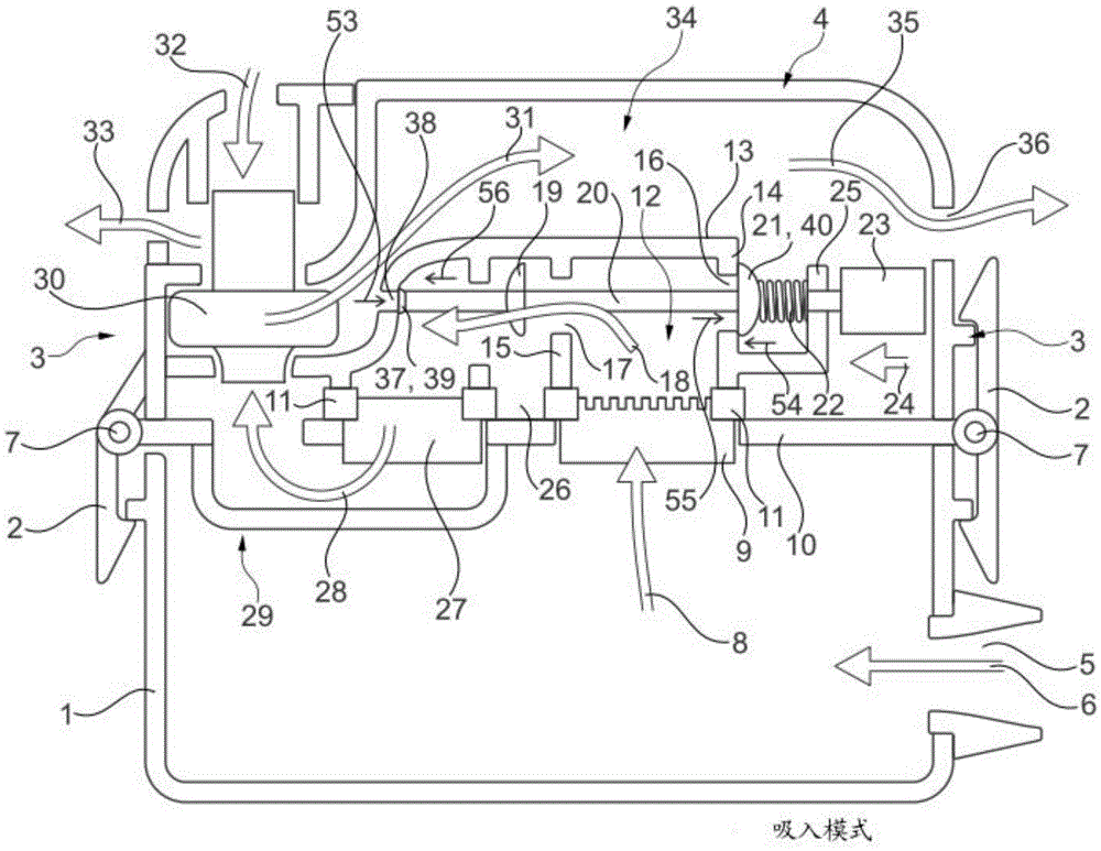
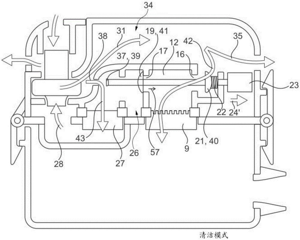
[0038] exist figure 1 A vacuum cleaner is generally shown in FIG. 2 , which is composed of a main filter 27 and an upstream pre-filter 9 . However, the present invention is not limited thereto. It can likewise have two main filters 27, which are then correspondingly associated with a cleaning unit, as it is in the form of cleaning unit 3 figure 1 as shown in.

[0039] Therefore, according to the present invention figure 1 and 2 The cleaning device can also be transferred to the double filter device according to DE 10101219 A1.

[0040] Accordingly, the invention is not restricted to cleaning a single main filter 27 .

[0041] In the exemplary embodiment shown, the vacuum cleaner essentially consists of a dust-containing container 1 which is detachably connected via a lateral cover 2 to a cleaning unit 3 arranged thereon. A cover unit 4 is detachably arranged on the cleaning unit 3 .

[0042] Contaminated air flows in the direction of the arrow 6 via the inlet 5 into ...


PUM


Abstract

A method for operating a suction-type cleaner, in which, in a manner controlled in the filter dedusting position by an electromagnetically actuated switchover valve arrangement (19, 20, 21), at least one filter (9), through which the dirt-laden air flow passes, is dedusted in the opposite direction to said air flow, and the dirt-laden suction air from the dirt-collecting container (1) firstly passes through the at least one filter (9) which is adjoined, in the flow direction, by a suction chamber (12), which is adjoined downstream by an intermediate chamber (26) which is arranged on the suction side of the turbine (30), and a pressure chamber (34) is arranged downstream of the turbine (30), wherein, in order to reduce the actuating force of the switchover valve arrangement (19, 20, 21) in the dedusting position of the suction-type cleaner, the pressure between the pressure chamber (34) and the intermediate chamber (26) is equalised.

Description

technical field [0001] The invention relates to a method for operating a vacuum cleaner with a cleaning control device for filters according to the preamble of patent claim 1 . Such a cleaning control device is known from the object of DE 10101219 A1, in which however the vacuum cleaner is provided with two valves for controlling the cleaning of the filter and a separate filter. Background technique [0002] Accordingly, each filter to be cleaned (filter half) is associated with its own switching valve. [0003] Each switching valve is electromagnetically actuated and consists of a lifting magnet which actuates a valve stem on which two valve slides arranged at a distance from one another are arranged. [0004] In one of the travel positions, therefore, there is an operating position, which means that the two filter halves are passed through by contaminated air. [0005] In contrast, if the lifting magnet is actuated, the valve stem is thus lifted and the switching valve i...

Claims


Application Information

Patent Timeline
IPC IPC(8): A47L9/20A47L5/36
CPCA47L5/365A47L9/20A47L5/36A47L9/2857
Inventor 安德斯·佛恩森
Owner NILFISK
Why Eureka
Try Eureka