Exhaust gas purification device for internal combustion engine

An exhaust gas purification device and technology for exhaust gas purification, which are applied in the direction of exhaust gas device, diagnosis device of exhaust gas treatment device, internal combustion piston engine, etc., can solve problems such as inability to purify NOx

Active Publication Date: 2017-08-29
TOYOTA JIDOSHA KK
View PDF1 Cites 0 Cited by
  • Summary
  • Abstract
  • Description
  • Claims
  • Application Information

AI Technical Summary

Problems solved by technology

As a result, if the second NOx purification method is used because the temperature of the exhaust purification catalyst is lower than the limit temperature, and the rich air-fuel ratio control is not performed for a long time, the stored NOx cannot be released from the exhaust purification catalyst, and thus It becomes impossible to purify NOx well
[0005] In other words, even if it is decided to use the first NOx purification method or the second NOx purification method according to a certain criterion, it may not be possible to perform good NOx purification.

Method used


Image

  • Exhaust gas purification device for internal combustion engine
  • Exhaust gas purification device for internal combustion engine
  • Exhaust gas purification device for internal combustion engine

Examples


Embodiment Construction

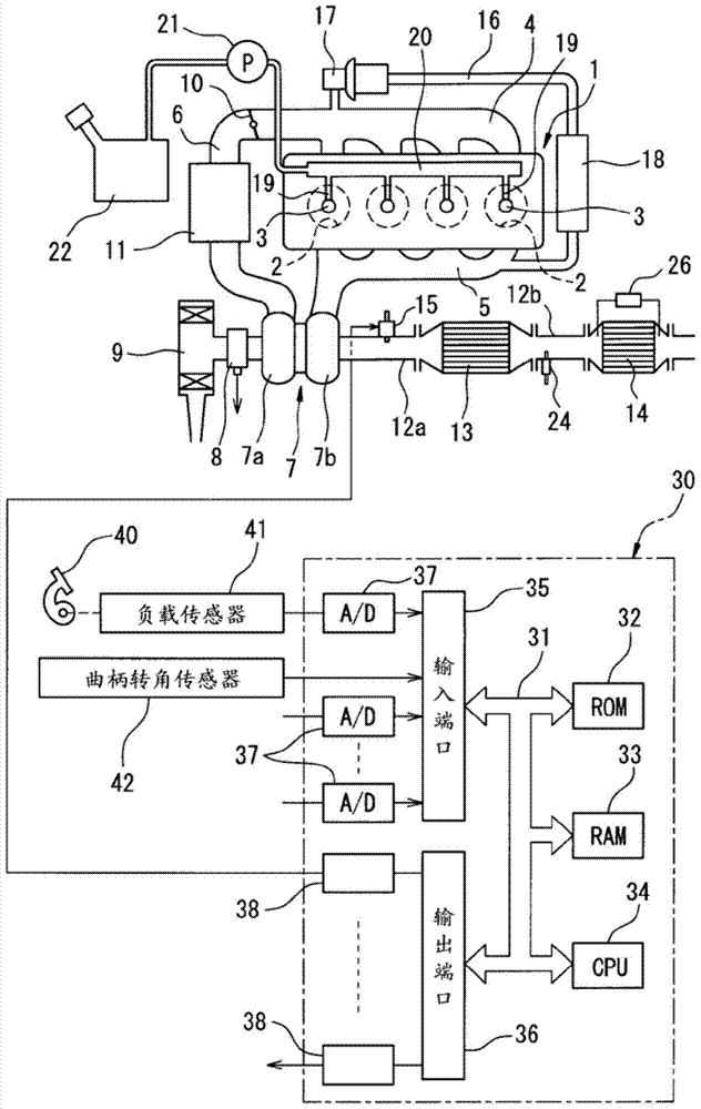
[0042] figure 1 Shows the overall view of a compression ignition internal combustion engine.

[0043] Reference figure 1 1 shows the main body of the internal combustion engine, 2 shows the combustion chamber of each cylinder, 3 shows an electronically controlled fuel injection valve for injecting fuel into each combustion chamber 2, 4 shows the intake manifold, 5 shows Exhaust manifold. The intake manifold 4 is connected to the outlet of the compressor 7 a of the exhaust turbocharger 7 via the intake line 6, and the inlet of the compressor 7 a is connected to the air cleaner 9 via the intake air amount detector 8. A throttle valve 10 driven by an actuator is arranged in the intake pipe 6, and a cooling device 11 for cooling the intake air flowing in the intake pipe 6 is arranged around the intake pipe 6. in figure 1 In the illustrated embodiment, the engine cooling water is introduced into the cooling device 11, and the engine cooling water is used to cool the intake air.

[004...


PUM


Abstract

The present invention provides an exhaust purification device for an internal combustion engine, wherein an exhaust purification catalyst and a hydrocarbon feed valve are arranged in an exhaust passage of the internal combustion engine. The first NOx purification method is performed when the temperature of the exhaust purification catalyst belongs to the first catalyst temperature region (I), and the second NOx purification method is performed when the temperature of the exhaust purification catalyst belongs to the second catalyst temperature region (II). When the temperature of the exhaust purification catalyst belongs to the region (IIP) close to the temperature region of the first catalyst in the second catalyst temperature region, the temperature of the exhaust purification catalyst is raised so that the region to which the temperature of the exhaust purification catalyst belongs is closer to the first catalyst temperature region. The temperature zone shifts, whereby the NOx purification method used is switched from the second NOx purification method to the first NOx purification method.

Description

Technical field [0001] The present invention relates to an exhaust purification device of an internal combustion engine. Background technique [0002] An exhaust purification device of an internal combustion engine is known in which an exhaust purification catalyst is arranged in the exhaust passage of the internal combustion engine, and a hydrocarbon feed valve is arranged in the exhaust passage of the internal combustion engine upstream of the exhaust purification catalyst. The exhaust gas flow surface of the exhaust purification catalyst A precious metal catalyst is supported and an alkaline exhaust gas flow surface portion is formed around the precious metal catalyst. The exhaust purification catalyst has an amplitude and a predetermined amplitude if the concentration of hydrocarbons flowing into the exhaust purification catalyst falls within a predetermined range. The periodic vibration within the range reduces the NOx contained in the exhaust gas, and has the property of in...

Claims


Application Information

Patent Timeline
Patent Type & Authority Patents(China)
IPC IPC(8): F01N3/36F01N3/08
CPCF01N3/36F01N3/0814F01N3/0842F01N3/0871F01N11/002F01N2900/1602Y02T10/40F01N3/2066F01N2550/02F01N2610/03F02D41/0245
Inventor 野木嘉人野崎雄介羽场优树
Owner TOYOTA JIDOSHA KK
Why Eureka
Try Eureka