

Method and apparatus for exhaust gas control of an internal combustion engine
- Summary
- Abstract
- Description
- Claims
- Application Information
AI Technical Summary
Benefits of technology
Problems solved by technology
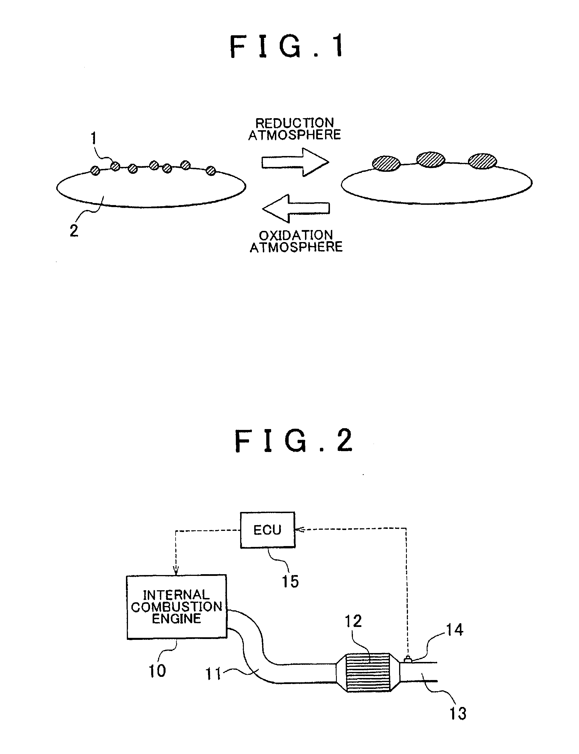
Method used
Image

Examples
first embodiment
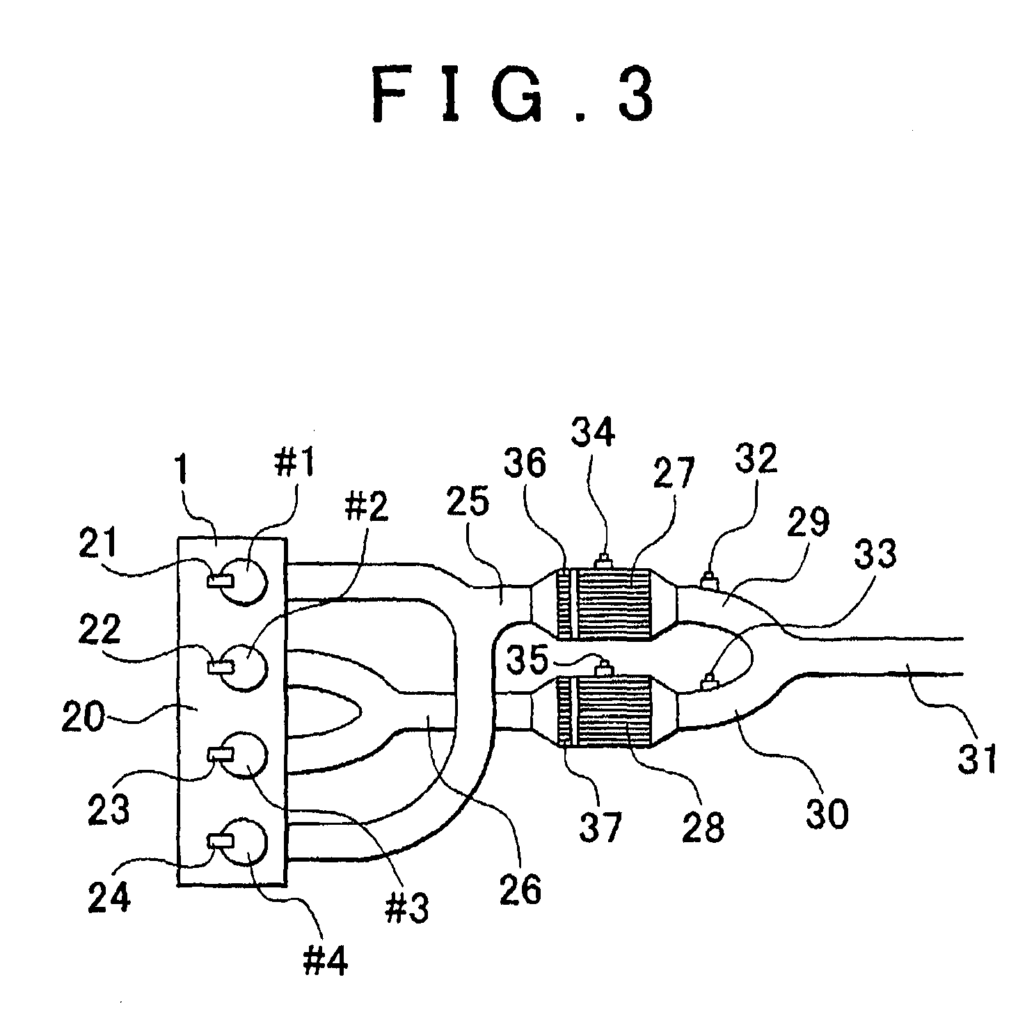
[0034]FIG. 2 is a view that schematically shows an exhaust gas control apparatus according to the invention.
[0035]As shown in FIG. 2, the exhaust side of an internal combustion engine 10 is connected via an exhaust passage 11 to a NOx purification catalyst 12 that contains Cu as a catalyst metal, and the outlet portion of the NOx purification catalyst 12 is further connected to an exhaust passage 13. In addition, in the first embodiment of the invention, a NOx sensor 14 (degradation degree estimating unit) is installed in the exhaust passage 13. The NOx sensor 14 is used to detect NOx in exhaust gas flowing out from the NOx purification catalyst 12. Then, the air-fuel ratio of exhaust gas may be adjusted by an electronic control unit (ECU) 15 (air-fuel ratio control unit) on the basis of the amount of NOx in exhaust gas, detected by the NOx sensor 14.
[0036]According to the present embodiment, during normal times, the air-fuel ratio of exhaust gas flowing into the NOx purification ca...
second embodiment
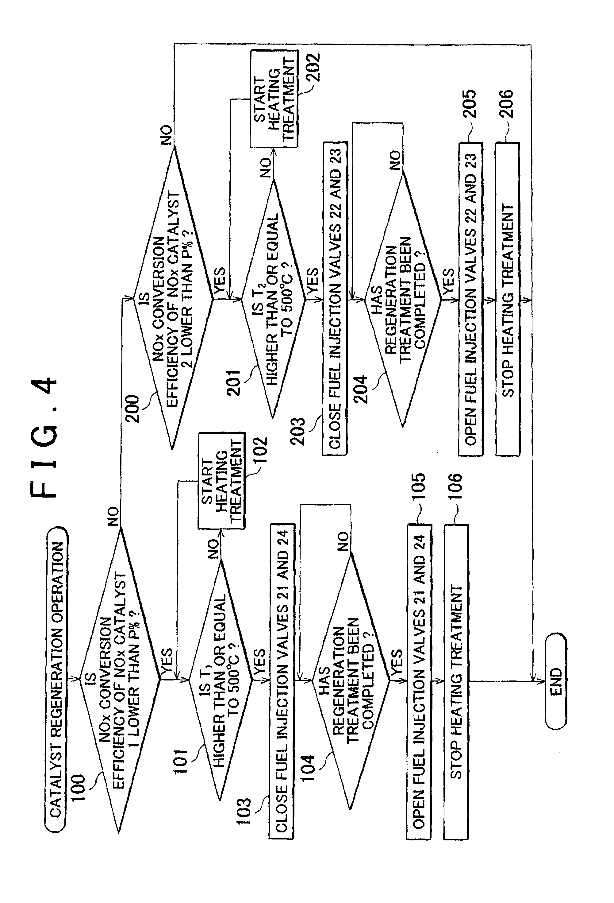
[0043]FIG. 3 is a view that schematically shows the exhaust gas control apparatus according to the invention. In FIG. 3, an internal combustion engine 20 has a first cylinder #1, a second cylinder #2, a third cylinder #3 and a fourth cylinder #4. Fuel injection valves 21, 22, 23 and 24 are provided in correspondence with the respective cylinders. In addition, the first cylinder and the fourth cylinder are connected to a first NOx purification catalyst 27 via an exhaust passage 25, and the second cylinder and the third cylinder are connected to a second NOx purification catalyst 28 via an exhaust passage 26. Then, the outlet portion of the first NOx purification catalyst 27 and the outlet portion of the second NOx purification catalyst 28 are respectively connected to exhaust passages 29 and 30, and these exhaust passages merge into a common exhaust passage 31 on the further downstream side.
[0044]In addition, in the exhaust gas control apparatus according to the second embodiment of ...
PUM
 Abstract
Description
Claims
Application Information