Apparatus for producing nanocarbon, method for producing nanocarbon and method for collecting nanocarbon

Inactive Publication Date: 2006-10-26
NEC CORP
View PDF4 Cites 5 Cited by
  • Summary
  • Abstract
  • Description
  • Claims
  • Application Information

AI Technical Summary

Benefits of technology

[0023] According to the present invention, there is provided a method of recovering nanocarbon including, after nanocarbon is generated, moistening and recovering the nanocarbon. According to the recovery method relating to the present invent

Problems solved by technology

However, as the result of the study of this method by the inventors, it has become apparent that it is difficult to recover generated sooty material.
In particular, carbon nanohorn assemb

Method used


Image

  • Apparatus for producing nanocarbon, method for producing nanocarbon and method for collecting nanocarbon
  • Apparatus for producing nanocarbon, method for producing nanocarbon and method for collecting nanocarbon
  • Apparatus for producing nanocarbon, method for producing nanocarbon and method for collecting nanocarbon

Examples


Example

First Embodiment

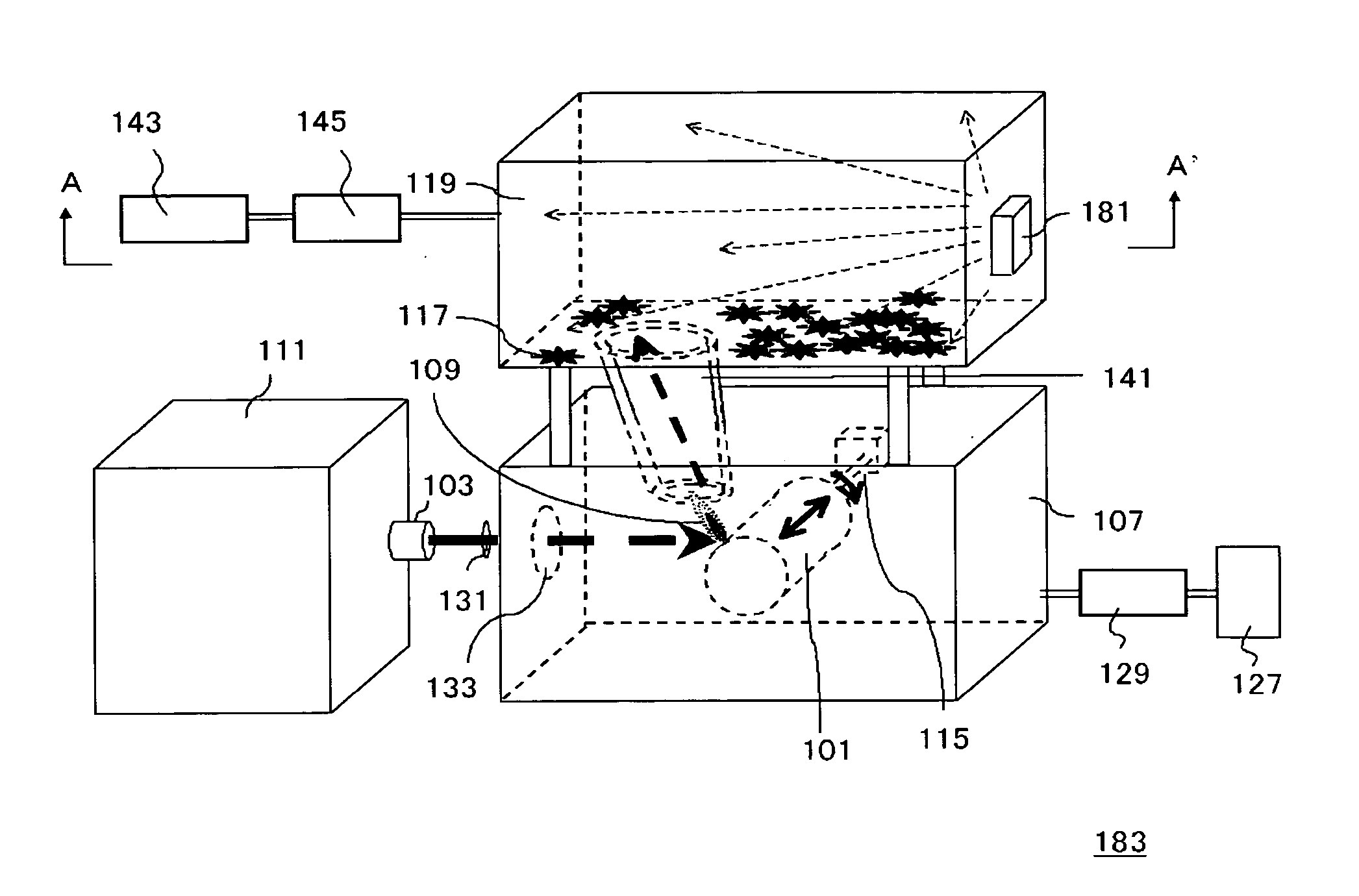
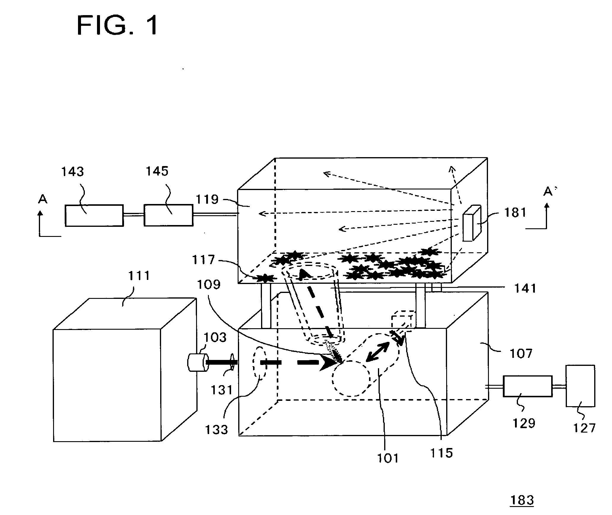
[0036] In the present embodiment, a chamber for recovering nanocarbon is provided in a nanocarbon manufacturing apparatus, and a spray device for moistening nanocarbon is provided at the chamber for recovering. FIG. 1 is a diagram showing a structure of a nanocarbon manufacturing apparatus 183 of the present embodiment. Note that, in this specification, FIG. 1 and the other drawings used for describing a manufacturing apparatus are schematic diagrams, and the sizes of respective constructional members do not necessarily correspond to actual dimensional ratio.

[0037] The nanocarbon manufacturing apparatus 183 of FIG. 1 has a manufacturing chamber 107, a nanocarbon recovery chamber 119, a carrier pipe 141, a laser light source 111, a ZnSe plano-convex lens 131, a ZnSe window 133, a rotation device 115, and a sprayer 181. Moreover, the nanocarbon manufacturing apparatus 183 has an inert gas feeding unit 127, a flow meter 129, a vacuum pump 143, and a pressure gage 145....

Example

Second Embodiment

[0070] In the nanocarbon manufacturing apparatus 183 or the nanocarbon manufacturing apparatus 184 described in the first embodiment, the structure of the sprayer 181 may be made as follows. Here, the case of the nanocarbon manufacturing apparatus 184 of FIG. 3 will be described as an example.

[0071]FIG. 4 is a cross-sectional view of the nanocarbon manufacturing apparatus 184 in the B-B′ direction of FIG. 3, and is a diagram for explanation of the structure of the sprayer 181. In FIG. 4, the sprayer 181 has a tank 201, a feeding pipe 203, and a nozzle 205. The spray liquid 193 is received in the tank 201. Further, the feeding pipe 203 connects the tank 201 and the nozzle 205. A valve 209 for adjusting feeding of the spray liquid 193 from the tank 201 is provided at the feeding pipe 203. The nozzle 205 is formed in a watering pot shape having many pores 207. FIG. 5 is a perspective view showing a structure of the nozzle 205.

[0072] At the time of manufacturing the ...

Example

Third Embodiment

[0074] In the present embodiment, a structure of the bottom of the recovery chamber is different from that of the nanocarbon manufacturing apparatus described in the first or second embodiment. Hereinafter, the case of the nanocarbon manufacturing apparatus 184 described in the firs embodiment will be described as an example. FIG. 6 is a diagram showing a nanocarbon manufacturing apparatus 185 relating to the present embodiment.

[0075] In the nanocarbon manufacturing apparatus 185, the bottom face of a nanocarbon recovery chamber 187 is inclined. Thereby, the carbon nanohorn assemblies 117 moistened by a liquid sprayed from the sprayer 181 move in a lower direction at the bottom of the nanocarbon recovery chamber 187. Therefore, the carbon nanohorn assemblies 117 can be gathered at the lower region at the bottom of the nanocarbon recovery chamber 187. Therefore, the carbon nanohorn assemblies 117 can be more easily recovered.


PUM


Abstract

In a nanocarbon manufacturing apparatus (183), a spray (181) is provided at a side face of a nanocarbon recovery chamber (119), and a mist (195) is sprayed on the entire nanocarbon recovery chamber (119) from the spray (181).

Description

TECHNICAL FIELD [0001] The present invention relates to a nanocarbon manufacturing apparatus, and methods of manufacturing and recovering a nanocarbon. BACKGROUND ART [0002] In recent years, technological applications of nanocarbon have been actively under review. Nanocarbon means carbon material having a nanoscale microstructure which is typified by a carbon nanotube, a carbon nanohorn, or the like. Among these, carbon nanohorn has a tube-shaped structure in which one edge of a carbon nanotube that a graphite sheet is made round cylindrically has a conical shape, and is expected to be applied to various technical fields from the unique characteristic thereof. Usually, carbon nanohorns form a carbon nanohorn assembly so as to gather in a form in which the conical portions are projected like a horn at the surface centering around the tube by van der Waals force acting between conical portions. [0003] It has been reported that a carbon nanohorn assembly is manufactured by a laser vapo...

Claims


Application Information

Patent Timeline
IPC IPC(8): D01F9/12B01J19/08C01B31/00B01J19/12C01B31/02
CPCB01J19/121B01J2219/0886C01B31/0293B82Y40/00C01B31/0226B82Y30/00C01B32/16C01B32/18
Inventor AZAMI, TAKESHIKASUYA, DAISUKEYOSHITAKE, TSUTOMUKUBO, YOSHIMIIIJIMA, SUMIOYUDASAKA, MASAKO
Owner NEC CORP
Why Eureka
Try Eureka