Multifunctional glue applying equipment

A multi-functional, gluing technology, applied in the direction of coating, liquid coating device on the surface, etc., can solve the problems of high labor intensity for operators, affecting the production process, and low degree of automation, so as to reduce labor intensity and improve High work efficiency and high degree of automation

Inactive Publication Date: 2015-12-16
天津天美环保科技有限公司
View PDF6 Cites 11 Cited by
  • Summary
  • Abstract
  • Description
  • Claims
  • Application Information

AI Technical Summary

Problems solved by technology

However, when a batch of objects needs to be sprayed on the same place, if you rely on manual spraying one by one, it will lead to uneven glue spraying, and it will make the labor intensity of the operators high, the work is boring, and the entire assembly line Inefficiency seriously affects the entire production process
The existing glue spraying or gluing equipment has a low degree of automation. Usually, after the glue spraying process, the glued packaging box is sent to the glue scraping equipment for smoothing, removing excess glue, and controlling the glue layer to a predetermined thickness. within the range
In this way, glue spraying equipment and glue scraping equipment are installed at the same time, and the purchase cost is high. Moreover, during the docking process of the two equipment, the packaging box often shifts, making the thickness control of the glue layer inaccurate.
In addition, the feeding end of the existing glue spraying machine sometimes stacks the packaging boxes together. After reaching the spray gun, the upper box is sprayed with glue, and the lower box is not glued. If the inspection is not careful, it will be transported to The next process will result in waste

Method used


Image

  • Multifunctional glue applying equipment
  • Multifunctional glue applying equipment
  • Multifunctional glue applying equipment

Examples


Embodiment Construction

[0025] Specific embodiments of the present invention will be described in detail below in conjunction with the accompanying drawings.

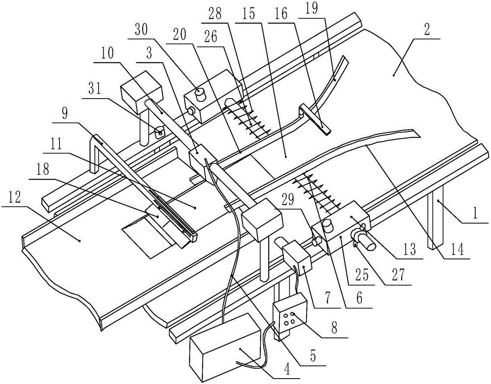
[0026] A multifunctional gluing equipment, such as figure 1 As shown, it includes a frame 1, a conveyor belt 2, a glue gun 3, a glue source 4, and a glue outlet pipe 5 connected to the glue source 4; in addition, it also includes a box sorting device 6, an induction device 7, a control box 8, and a glue scraping device 9 , the glue gun fixed frame 10 that is arranged on the conveyer belt 2 top and the holding tray 12 that is provided with feed chute 11; Two baffle plates 14, these two baffle plates 14 are arranged on the top of the conveyor belt 2, and a box sending channel 15 is formed between the two; the corresponding box sending channel 15 is provided with a blocking mechanism 16 on the said baffle plate 14; The feed trough 11 is set corresponding to the box delivery channel 15; as Figure 4 As shown, the glue scraping device 9 includes ...


PUM


Abstract

The invention provides multifunctional glue applying equipment which comprises a machine frame, a conveyor belt, a glue gun, a glue source and a glue discharging pipe communicated with the glue source. The multifunctional glue applying equipment further comprises a box arranging device, an induction device, a control box, a glue scraping device, a glue gun fixing frame arranged above the conveyor belt and a containing disc provided with a feeding groove. The box arranging device forms a box feeding channel. A blocking mechanism is arranged at the portion, corresponding to the box feeding channel, of the box arranging device. The feeding groove of the containing disc corresponds to the box feeding channel. The glue scraping device comprises a fixing frame and a scraper arranged at the portion, corresponding to the feeding groove, of the fixing frame. One end of the glue discharging pipe is connected with the glue source, and the other end of the glue discharging pipe is connected with the glue gun. The glue gun corresponding to the box feeding channel is installed on the glue gun fixing frame. The induction device is arranged at the position, close to the glue gun, of the machine frame. The glue gun and the induction device are connected with the control box. The multifunctional glue applying equipment can automatically correct the position of box bodies, can prevent the box bodies from being stacked, can automatically spray gun and scrape away excessive glue, and is multifunctional and high in integration degree.

Description

technical field [0001] The invention belongs to the technical field of gluing equipment, and in particular relates to a multifunctional gluing equipment. Background technique [0002] The mobile phone packaging box usually includes an upper case and a lower case, and the upper case and the lower case are snapped together to wrap the mobile phone inside the case. In the production design, in order to increase the three-dimensionality and strength of the shell, the lower shell in the usual sense is used as the middle bottom shell, and then a lower bottom shell is placed on the lower part of the middle bottom shell, and the lower bottom shell and the middle bottom shell are glued together. Together, the traditional glue spraying is to manually spray the glue on the position where the glue needs to be sprayed, and then carry out the follow-up operation. However, when a batch of objects needs to be sprayed on the same place, if you rely on manual spraying one by one, it will lea...

Claims


Application Information

Patent Timeline
Patent Type & Authority Applications(China)
IPC IPC(8): B05C5/00B05C13/02B05C11/10B05C11/04
Inventor 仝宝旺
Owner 天津天美环保科技有限公司
Why Eureka
Try Eureka