
Coater and its oven unit

A coating machine and oven technology, which is applied to the surface coating liquid device, coating, pretreatment surface, etc., can solve the problems of uneven drying, many processing parts, waste of resources, etc., to reduce uneven drying , less processing parts, and the effect of reducing heat loss

Active Publication Date: 2017-11-21
DONGGUAN ARECONN PRECISION MACHINERY
View PDF2 Cites 1 Cited by
  • Summary
  • Abstract
  • Description
  • Claims
  • Application Information

AI Technical Summary

Problems solved by technology

[0004] The purpose of the present invention is to provide a coating machine and its oven unit, which solves the problem that the existing coating machine oven unit has a certain dead angle in the circulating air field, the air flow is not smooth, and it is easy to cause uneven drying and excessive heat loss. Waste, and the processing parts are more, the problem of inconvenient assembly

Method used


Image

  • Coater and its oven unit
  • Coater and its oven unit
  • Coater and its oven unit

Examples


Embodiment 1

[0025] refer to Figure 4 to Figure 9 , the present embodiment provides a coating machine, especially an oven unit of the coating machine, the oven unit of the coating machine includes an integral frame with upper and lower layers.

[0026] The upper layer of the overall frame is provided with an upper wind chamber 5 and a lower wind chamber 6 extending along the length direction of the oven unit, and the inner diameters of the upper wind chamber 5 and the lower wind chamber 6 gradually narrow along the air supply direction, further, the upper wind chamber 5 and the lower wind chamber 6 The inner diameter may be constant along the air supply direction. Between the upper wind chamber 5 and the lower wind chamber 6 is the substrate transmission channel, and the upper wind chamber 5 and the lower wind chamber 6 can blow and dry the upper surface and the lower surface of the substrate respectively; further, the upper wind chamber 5 and the lower wind chamber 6 face the substrate ...

Embodiment 2

[0031] See Figure 10 , the difference between this embodiment and the first embodiment is that the oven unit can also be based on the first embodiment Figure 4 Symmetrical structure. That is to say, the circulation fan 4 and the static pressure box 8 can also be arranged on the other side of the overall frame.


PUM


Abstract

A coating machine and its oven unit, comprising an overall frame with upper and lower layers, the lower layer of the overall frame is provided with a circulation pipe, a heating system, and a fresh air outlet communicating with the air return port, and the upper layer of the overall frame is provided with an upper air chamber and a lower air chamber. The side of the overall frame is equipped with a circulating fan and a static pressure box. After the hot air is blown out from the upper air chamber and the lower air chamber to dry the substrate, part of the air is discharged from the exhaust port, and the other part of the air enters the circulation pipe through the return air port, mixes with the fresh air entering the circulation pipe from the fresh air port, and is heated by the heating system It is hot air, driven by the circulating fan, the hot air enters the static pressure box, and then enters the upper and lower chambers from the air inlet of the upper and lower chambers, and repeats the above to form a circulating air, which solves the problem of the prior art. There is a dead angle problem in the wind field, and the circulating air is smoother, which can evenly dry the substrate, reduce heat loss, save costs, and improve production efficiency.

Description

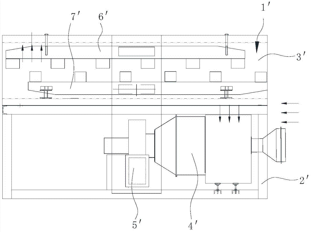
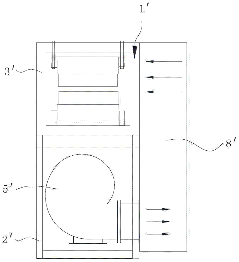
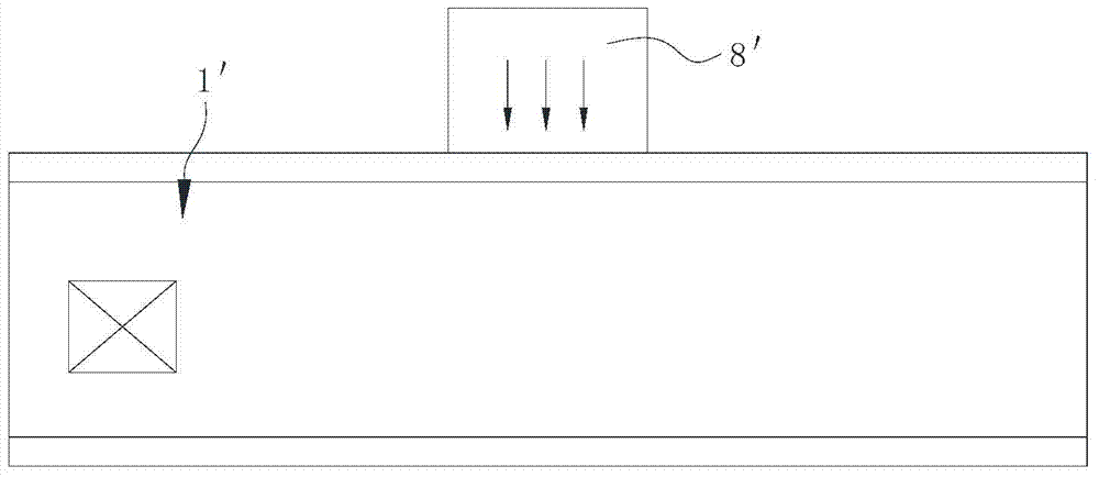
technical field [0001] The present invention relates to coater equipment, and more particularly to coaters and oven units therefor. Background technique [0002] Coating machines are widely used in many new industries, such as optical fields, electronics fields, aerospace fields, and protective film adhesive tape fields. Coat the rolled substrate with a layer of glue, paint or ink with specific functions, and dry it After rewinding. [0003] see Figure 1 to Figure 3 , the oven unit 1' of the existing coating machine, the frame 2' and the box body 3' are separately arranged on the structure, the static pressure box 8' is arranged in the middle part of the frame 2', the upper air duct 6' and the lower air duct The air inlet of 7' provides heated air, and the heated air is scattered from the middle of the upper air duct 6' and the lower air duct 7' to both ends respectively, and then blows out to the substrate for drying, and the cooled air flows from the upper air duct 6' a...

Claims


Application Information

Patent Timeline
Patent Type & Authority Patents(China)
IPC IPC(8): B05D3/04
Inventor 刘碧刚杨勇
Owner DONGGUAN ARECONN PRECISION MACHINERY
Learn More