Fluidized bed dryer

A fluidized bed drying and fluidized bed technology, applied in the direction of drying solid materials, drying gas arrangement, heating to dry solid materials, etc., can solve problems such as falling, affecting the overall performance of the fluidized bed, and blocking the outlet of the air distribution plate

Inactive Publication Date: 2019-05-14
丹阳市宏光机械有限公司
View PDF3 Cites 0 Cited by
  • Summary
  • Abstract
  • Description
  • Claims
  • Application Information

AI Technical Summary

Problems solved by technology

[0003] In the fluidized bed dryer in the prior art, when the wet material enters the larger space inside the fluidized bed, the space suddenly becomes larger, and the wet material mixed together forms a material block due to the mutual viscous stress. , the hot air cannot blow up the agglomerated material to achieve the drying effect, and the agglomerated material will fall to the bed body of the fluidized bed, blocking the outlet of the air distribution plate and affecting the overall performance of the fluidized bed

Method used


Image

  • Fluidized bed dryer

Examples


Embodiment Construction

[0017] In order to specifically illustrate the technical solution of the present invention, the present invention will be explained through specific embodiments below.

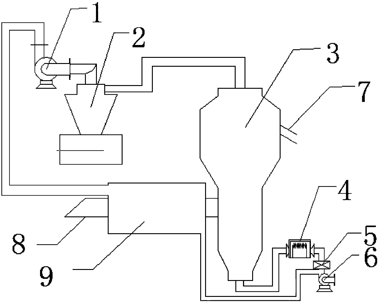
[0018] figure 1 Shown is a schematic diagram of a fluidized bed dryer designed by the present invention. A wet material inlet pipe 8 is provided on the left side wall of the fluidized bed body 3, a dry material outlet pipe 7 is provided on the right side wall, the top outlet is connected to the cyclone separator 2 pipeline, and the bottom inlet is connected to the heater 4 outlet pipeline. The heater 4 is connected to the filter 5 through pipelines, and the filter 5 is connected to the blower 6 through pipelines. The top outlet of the cyclone separator 2 is connected to the induced draft fan. The air sent by the blower 6 is purified by the filter 5 and then enters the heater 4 to be heated. The heated air enters the fluidized bed body 3 to dry the wet material, and the dried waste gas enters the cyclone sepa...


PUM


Abstract

The invention relates to a drying device, in particular to a fluidized bed dryer. A fluidized bed body, a heater, an air blower, an induced draught fan and a cyclone separator are included; the two sides of the fluidized bed body are provided with a wet material inlet pipe and a dry material outlet pipe correspondingly; a bottom connection pipe of the fluidized bed body communicates with the heater which communicates with the air blower; a filter is arranged in a pipeline between the heater and the air blower; a top connection pipe of the fluidized bed body communicates with the cyclone separator; and a top outlet of the cyclone separator communicates with the induced draught fan. According to the fluidized bed dryer, the outer wall face of the wet material inlet pipe is sleeved with a boxbody, the inner wall of the box body and the outer wall of the wet material inlet pipe form a cavity, heat media flow through the cavity, wet materials are dried in advance, and therefore the defectsthat caking is caused when the wet materials enter a bed body in the prior art and drying unevenness is caused, and discharging of products is affected are reduced.

Description

technical field [0001] The invention relates to a drying device, in particular to a fluidized bed dryer. Background technique [0002] Fluidized bed technology (also known as fluidized technology) originated in 1921. Fluidized bed dryers are also called fluidized bed dryers. Fluidized drying refers to the process in which the drying medium makes solid particles dry in a fluidized state. Its working principle is: the granular solid material is fed into the fluidized bed dryer by the feeder, and the filtered clean air is heated by the heater and sent to the bottom of the fluidized bed by the blower, and is in contact with the solid material through the air distribution plate, and is solid Form a strong turbulent flow, fully mix with hot air to absorb heat, exchange heat between gas and solid, and achieve the purpose of drying. After drying, the material is discharged through the discharge port, and the waste gas is discharged from the top of the fluidized bed, and the materia...

Claims


Application Information

Patent Timeline
Patent Type & Authority Applications(China)
IPC IPC(8): F26B3/08F26B1/00F26B21/00
Inventor 郦雷敏
Owner 丹阳市宏光机械有限公司
Why Eureka
Try Eureka