Pulley puller

A drawing device and pulley technology, used in metal processing, metal processing equipment, manufacturing tools, etc., can solve the problems of difficult installation of drawing tools, small space, difficult disassembly of crankshaft pulleys, etc., to achieve high production efficiency, easy installation, Good general effect

Active Publication Date: 2018-01-30
GUANGXI YUCHAI MASCH CO LTD
View PDF8 Cites 0 Cited by
  • Summary
  • Abstract
  • Description
  • Claims
  • Application Information

AI Technical Summary

Problems solved by technology

[0005] The purpose of the present invention is to provide a pulley puller with a simple and reasonable structure. The pulley pulley uses the pulley groove as the clamping part. The pulley is easy to install and has good versatility. Difficult to install and disassemble the crankshaft pulley, it becomes easy when the crankshaft pulley needs to be disassembled, the production efficiency is high, and the efficiency of after-sales service is effectively improved

Method used


Image

  • Pulley puller
  • Pulley puller
  • Pulley puller

Examples


Embodiment Construction

[0017] The specific embodiments of the present invention will be described in detail below in conjunction with the accompanying drawings, but it should be understood that the protection scope of the present invention is not limited by the specific embodiments.

[0018] Unless expressly stated otherwise, throughout the specification and claims, the term "comprise" or variations thereof such as "includes" or "includes" and the like will be understood to include the stated elements or constituents, and not Other elements or other components are not excluded.

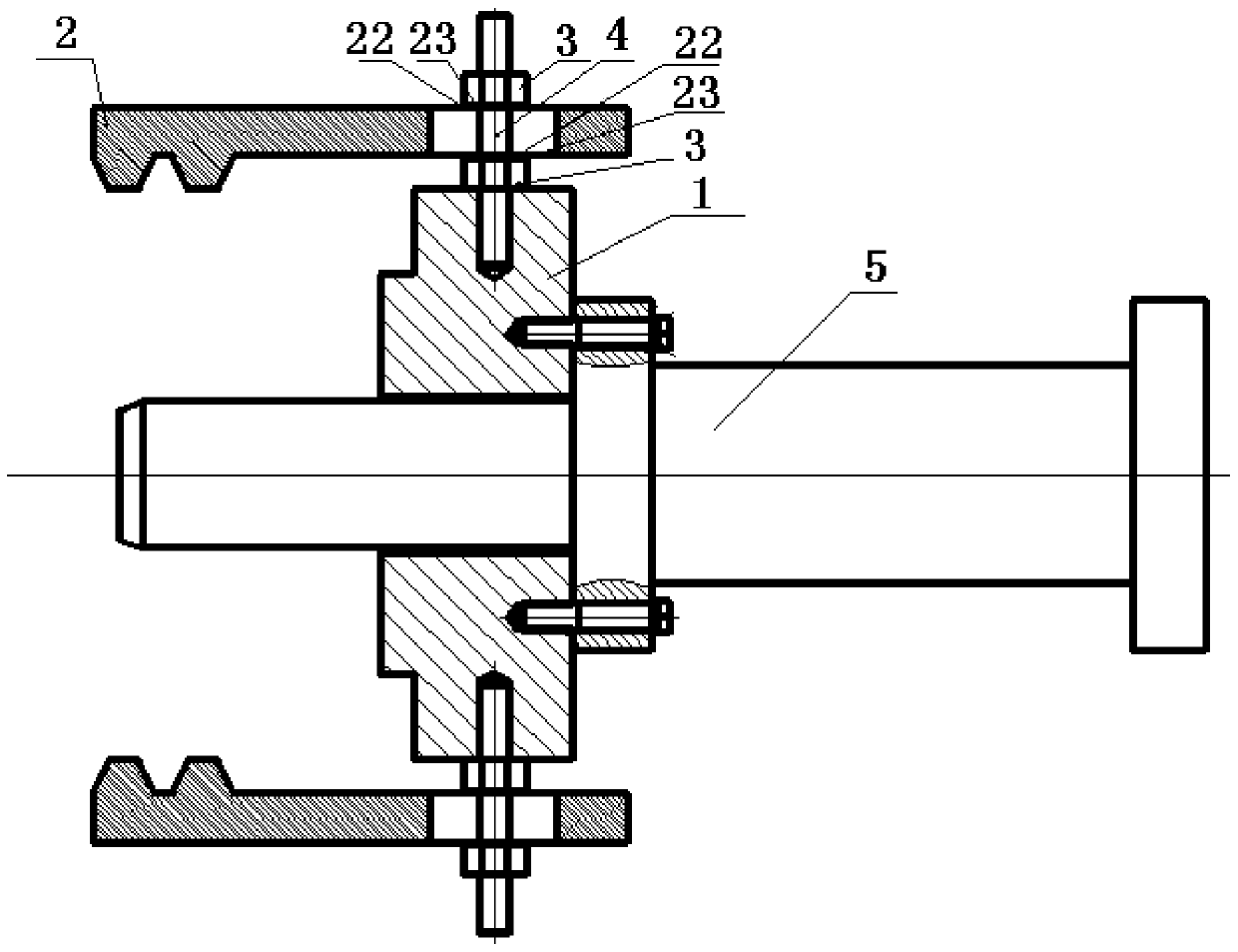
[0019] Such as figure 1 As shown, the specific structure of the pulley pulling device according to the specific embodiment of the present invention includes: installing a positioning block 1 , a clamping block 2 , an adjusting nut 3 , a stud 4 and a hydraulic pump 5 . Among them, the installation positioning block 1 has a boss matching the inner circle of the pulley, which is convenient for the assembly and positioning of ...


PUM


Abstract

The invention discloses a belt pulley drawing device. The belt pulley drawing device comprises an installing-positioning block, a hydraulic pump or a jack and clamping blocks, wherein a shaft hole is formed in the center of the installing-positioning block, the installing-positioning block comprises a rectangular installing base body and a belt pulley inner circle positioning boss protruding out of the front face of the rectangular installing base body, the hydraulic pump or the jack is fixed to the back face of the rectangular installing base body, the shaft of the hydraulic pump or the jack penetrates through the central shaft hole formed in the installing-positioning block so as to tightly abut against a belt pulley shaft, the clamping blocks are arranged on two sides of the installing-positioning block in a paired mode, and clamping connection flanges matched with belt pulley grooves are designed on the inner side faces of the outer ends of the clamping blocks. The belt pulley drawing device uses the belt pulley grooves as clamping positions and is easy to install and good in universality, the problem that a crankshaft belt pulley is difficult to dismount due to small space and difficult drawing tool installation is solved, dismounting of the crankshaft belt pulley becomes very easy when being needed, production efficiency is high, and after-sales service efficiency is effectively improved.

Description

technical field [0001] The invention relates to the field of engine after-sales service or engine assembly test, in particular to a belt pulley pulling device. Background technique [0002] At present, during the after-sales service of the engine or the assembly test of the engine, it is often found that the engine has "three leaks", especially the oil leakage in the front gear chamber, or the phenomenon of wrongly installing the crankshaft pulley, and the engine crankshaft pulley needs to be removed. And the crankshaft and the crankshaft pulley often adopt interference fit, the gap between the crankshaft pulley and the gear chamber is narrow, and the inner cavity space of the crankshaft pulley is small. [0003] In the current crank pulley puller, the installation plate is installed in the inner cavity of the crank pulley or between the crank pulley and the gear chamber. The inner cavity of the crank pulley is small, the gap between the crank pulley and the gear chamber is ...

Claims


Application Information

Patent Timeline
Patent Type & Authority Patents(China)
IPC IPC(8): B23P19/027B23P19/02
CPCB23P19/02B23P19/025B23P19/027
Inventor 李旭旺陈萍袁福吾刘伟琨寇世贵
Owner GUANGXI YUCHAI MASCH CO LTD
Why Eureka
Try Eureka