Heating plate welding device for automobile lamp

A technology for hot plate welding and automotive lamps, which is applied in the field of hot plate welding devices, can solve problems such as easy gaps in getting on and off the lampshade, falling off of the lampshade when getting on and off the car, and insufficient air tightness of the car lights, etc., to achieve efficient, fast welding and accurate welding , The effect of convenient loading and unloading

Inactive Publication Date: 2015-12-16
MAGNETI MARELLI AUTOMOTIVE COMPONENTS WUHU
6 Cites 3 Cited by

AI-Extracted Technical Summary

Problems solved by technology

[0002] At present, in the production process of car lights, the upper and lower car lights are usually bonded with solid glue, and when using solid glue for welding the car lights, the solid glue is more likely to fail due to changes in temperature or humidity, resulting in getting on an...

Method used

Fix the car lamp to be welded by the lower clamp seat 2 and the upper clamp seat 4, the welding surface of the car lamp of the lower clamp seat 2 and the upper clamp seat 4 is opposite, and then the heating plate 6 moves to the right to the upper mold base 7 and the lower The mold base 8 is close to the upper clamp base 2 and the lower clamp base 4 respectively. At this time, the push-up cylinder 12 and the push-down cylinder 10 are activated, and the welding surface of the car light is c...

Abstract

The invention provides a heating plate welding device for an automobile lamp. The automobile to be welded is fixed through a lower clamping seat and an upper clamping seat. The automobile lamp welding surface of the lower clamping seat is made to be opposite to the automobile lamp welding surface of the upper clamping seat. A heating plate moves rightwards to the position where an upper die holder and a lower die holder are close to the upper clamping seat and the lower clamping seat respectively. A push-up air cylinder and a push-down air cylinder are started at the moment. The automobile lamp welding surfaces make contact with the upper die holder and the lower die holder. When the automobile lamp welding surfaces are heated and fused to a certain temperature, the heating plate is moved away, and finally the automobile lamp welding surface of the upper clamping seat and the automobile lamp welding surface of the lower clamping seat are in contact and are bonded, thereby being welded together. In addition, the upper clamping seat and the lower clamping seat are connected with an upper sliding rail and a lower sliding rail respectively, and therefore feeding and discharging can be conducted conveniently. The heating plate welding device is simple in structure, easy to operate, capable of welding the automobile lamp efficiently and rapidly, accurate in welding, high in strength and applicable to production, and the temperature of the heating plate is easy to control.

Technology Topic

Image

  • Heating plate welding device for automobile lamp
  • Heating plate welding device for automobile lamp
  • Heating plate welding device for automobile lamp

Examples

  • Experimental program(1)

Example Embodiment

[0013] In order to deepen the understanding of the present invention, the present invention will be described in further detail below in conjunction with examples. The examples are only used to explain the present invention and do not constitute a limitation on the protection scope of the present invention.
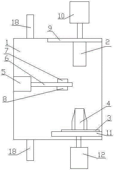
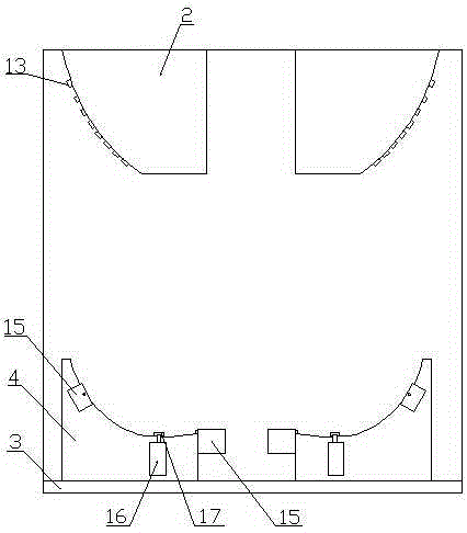
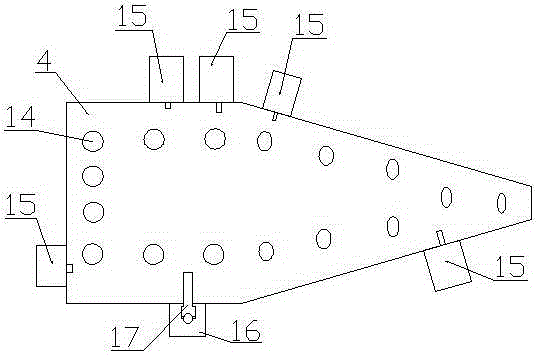
[0014] Such as Figure 1-3 As shown, this embodiment provides a hot plate welding device for automobile lights, including a welding chamber 1, an opening on the right side of the welding chamber 1, and two left-right symmetrical upper clamping seats are provided on the right side of the top of the welding chamber 1 2. A mounting plate 3 is provided on the right side of the bottom of the welding chamber 1, and two left-right symmetrical lower clamping seats 4 are provided on the mounting plate 3; the surface shape of the upper clamping seat 2 and the lower clamping seat 4 matches the shape of the vehicle lamp; A servo motor 5 is provided on the left side of the welding chamber 1, a heating plate 6 is provided on the right side of the servo motor 5, and upper and lower die holders 7 and 8 are respectively provided on the upper and lower sides of the right part of the heating plate 6. The upper die holder 7 and The surface shape of the lower mold base 8 respectively corresponds to the shape of the welding surface of the lamp; the upper clamp base 2 is provided with an upper slide rail 9 at the top, and a downward push cylinder 10 is provided above the upper slide rail 9; and the mounting plate 3 is provided below There is a sliding rail 11, and a push-up cylinder 12 is arranged under the sliding rail 11; the push-down cylinder 10 and the push-up cylinder 12 both extend out of the welding chamber 1. The upper clamping base 2 passes through a first suction tube 13 distributed therethrough, and the head of the first suction tube 13 is arranged on the lower surface of the upper clamping base 2. The second suction tube 14 is distributed through the lower clamp base 4, and the head of the second suction tube 14 is arranged on the upper surface of the upper clamp base 4; 5 clamping cylinders 15 that clamp inward are arranged around the lower clamp base 4 The front side of the lower clamp base 4 is also provided with a longitudinally telescopic lower clamp cylinder 16, and the head of the lower clamp cylinder 16 is provided with a rotating clamp column 17. Two suction pipes 18 are provided on the upper and lower sides of the left part of the welding chamber 1 to suck air in the welding chamber 1.
[0015] Fix the lamp to be welded by the lower clamp base 2 and the upper clamp base 4, and the welding surfaces of the lamp of the lower clamp base 2 and the upper clamp base 4 are opposite, and then the heating plate 6 is moved to the upper mold base 7 and the lower mold base 8 to the right Respectively close to the upper clamp base 2 and the lower clamp base 4, at this time the push-up cylinder 12 and the push-down cylinder 10 are activated, and the welding surface of the car light is in contact with the upper mold base 7 and the lower mold base, and the welding surface of the car light is heated When it melts to a certain temperature, remove the heating plate 6, and finally the welding surfaces of the upper clamping base 2 and the lower clamping base 4 are in contact with each other for bonding and welding together; and the upper clamping base 2 and the lower clamping base 4 are respectively connected with The upper slide rail 9 and the lower rail 11 can facilitate loading and unloading.
[0016] The structure of this embodiment is simple and easy to operate, can efficiently and quickly weld the vehicle lamp, the temperature of the heating plate is easy to control, the welding is accurate and the strength is high, and it is suitable for production.

PUM

no PUM

Description & Claims & Application Information

We can also present the details of the Description, Claims and Application information to help users get a comprehensive understanding of the technical details of the patent, such as background art, summary of invention, brief description of drawings, description of embodiments, and other original content. On the other hand, users can also determine the specific scope of protection of the technology through the list of claims; as well as understand the changes in the life cycle of the technology with the presentation of the patent timeline. Login to view more.

Similar technology patents

Finish forging die for forging aluminum alloy wheel

Owner:连云港宝石精密重工科技有限公司

One-time palletizing-burning tunnel kiln

ActiveCN102778126AEnergy-saving and efficient productionEasy loading and unloadingFurnace typesCeramic materials productionTunnel kilnTuyere
Owner:SHANDONG HENGXIANG MACHINERY

Classification and recommendation of technical efficacy words

  • Easy loading and unloading
  • Efficient welding

Handcart

InactiveCN107021432AEasy loading and unloadingMeet the height requirements of the tableLifting framesHand carts with multiple axesIndustrial engineeringPush ups
Owner:GUANGDONG UNIV OF TECH

Jaw structure for electrosurgical instrument

InactiveUS6905497B2Efficient weldingPrevent any substantial dehydrationSurgical instruments for heatingCoatingsBiomedical engineeringInstrumentation
Owner:ETHICON ENDO SURGERY INC

LTCC substrate component and eutectic sintering process method thereof

ActiveCN106876267AEfficient weldingAchieve high precision controlSemiconductor/solid-state device detailsSolid-state devicesSinteringCoating
Owner:LEIHUA ELECTRONICS TECH RES INST AVIATION IND OF CHINA

Welding method for small airborne rocket case

ActiveCN110064813AFast and accurate positioning of butt welding installationEfficient weldingArc welding apparatusProduct PartRocket
Owner:湖北三江航天江北机械工程有限公司

Current collecting disc welding production line

PendingCN112247356AEfficient weldingImprove feeding efficiencyPrimary cell manufactureAssembling battery machinesEngineeringCell fixing
Owner:江苏逸飞激光设备有限公司
Why Eureka
Try Eureka