Pressing dehydrator

A dehydrator and screw press technology, applied in the direction of presses, manufacturing tools, etc., can solve the problems of inconvenient operation, incomplete dehydration, etc., and achieve the effects of eliminating operation control, low operating power and low cost.

Inactive Publication Date: 2015-12-16
TAICANG KAI LUN AUTOMATION EQUIP CO LTD
View PDF9 Cites 0 Cited by
  • Summary
  • Abstract
  • Description
  • Claims
  • Application Information

AI Technical Summary

Problems solved by technology

At present, most of the existing screw press dehydrators need manual intermediate operation, which cannot achieve the purpose of convenient operation, and the actual dehydration of the screw blades may also lead to incomplete dehydration.

Method used


Image

  • Pressing dehydrator

Examples


Embodiment Construction

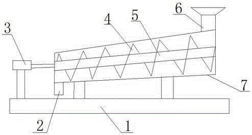
[0010] Such as figure 1 As shown, a screw press dehydrator of the present invention includes a frame 1, a feed port 6, a discharge port 2, a drive device 3, a screw shaft 5, a casing 7, and a screw blade 4, and the drive device 3 is fixed On the frame 1, the casing 7 is connected with the driving device 3, the screw shaft 5 is installed inside the casing 7 and driven to rotate by the driving device, the helical blade 4 is arranged on the helical column 5 in an encircling manner, and the casing 7 is connected to the screw column 5. The lower part of one end connected to the driving device 3 is provided with a discharge port 2, and the upper part of the other end is provided with a feed port 6. From the end of the feed port 6 to the end of the discharge port 2, it gradually shrinks, and the end of the feed port 6 of the casing 7 is high. At one end of the discharge port 2, the helical distance between the spiral blades 4 gradually decreases from the feed port 6 to the one end of...


PUM


Abstract

The invention discloses a spiral pressing dehydrator. The spiral pressing dehydrator comprises a rack, a feeding port, a discharging port, a driving device, a spiral shaft, a housing and spiral blades, wherein the driving device is fixed to the rack and connected with the housing; the spiral shaft is mounted in the housing and driven by the driving device to rotate; the spiral blades are arranged around the spiral shaft; the discharging port is formed in the lower part of the end, connected with the driving device, of the housing, and the feeding port is formed in the upper part of the other end of the housing; the housing is gradually constricted from the end with the feeding port to the end with the discharging port, and the end, with the feeding port, of the housing is higher than the end, with the discharging port, of the housing; the spiral distance between the spiral blades is gradually reduced from the end with the feeding port to the end with the discharging port. The spiral pressing dehydrator has the advantages that the housing structure and mounting are changed to achieve the effect of continuous dehydrating; the discharging port of the housing is lower than the feeding port of the housing, thus an object can move from the feeding port to the discharging port by virtue of the self gravity, and complex operation control in the whole moving process can be omitted. The spiral pressing dehydrator runs at a low speed, so that small power is needed for operating, and costs can be correspondingly reduced, and as a result, the characteristics of zero sludge residue, low emission and recycling can be achieved.

Description

technical field [0001] The invention relates to a pressing and dehydrating device, in particular to a screw pressing and dehydrating machine. Background technique [0002] The screw press dehydrator is a kind of solid-liquid separation equipment, which is composed of a filter cartridge jacket and a helical column. When the helical column rotates, it completes the filtration and dehydration of the flocculated sludge. It has the characteristics of low speed and low power consumption. The screw driving device is a single driving machine. When dehydrating, the screw shaft is rotated forward. When cleaning, the filter cartridge and the screw shaft are reversed. The combination of screw rotation and screw blades is used to achieve solid-liquid separation, and the sludge is sent to the dehydration process. The concentrated part of the machine is concentrated by the feed pressure in the concentrated part, and then transported to the filtering and pressing part by the spiral blade. ...

Claims


Application Information

Patent Timeline
Patent Type & Authority Applications(China)
IPC IPC(8): B30B9/14B30B15/30B30B15/32
Inventor 肖玉珍
Owner TAICANG KAI LUN AUTOMATION EQUIP CO LTD
Why Eureka
Try Eureka