
Cable reel assembly outbound distribution transmission line

A cable and transmission line technology, which is applied in the field of cable reel container outbound distribution transmission line, can solve the problems of large labor force, low distribution efficiency, and high labor intensity requirements, so as to reduce the number of labor, reduce the demand for personnel, and improve the supply. The effect of efficiency

Active Publication Date: 2017-06-16
STATE GRID SHANDONG ELECTRIC POWER +1
View PDF5 Cites 0 Cited by
  • Summary
  • Abstract
  • Description
  • Claims
  • Application Information

AI Technical Summary

Problems solved by technology

The entire operation process not only requires high labor intensity of workers, but also requires a large number of labor forces. Each operation is completed by multiple people and is intermittently connected, so the distribution efficiency is low.

Method used


Image

  • Cable reel assembly outbound distribution transmission line
  • Cable reel assembly outbound distribution transmission line
  • Cable reel assembly outbound distribution transmission line

Examples


Embodiment approach 1

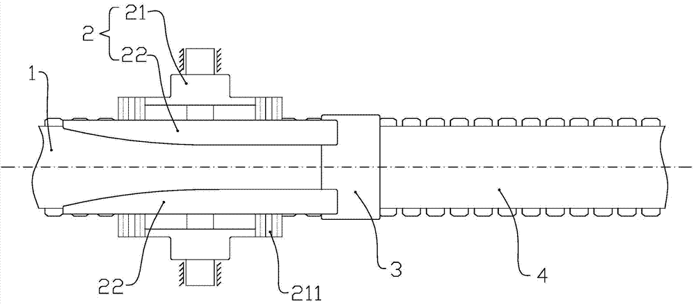
[0043] like Figure 1 to Figure 3The shown one cable reel container outbound distribution transmission line includes a first conveyor belt 1 , a guide unit 2 , a transition support 3 and a second conveyor belt 4 . The guide unit 2 includes two driving slides 21 and guide arms 22 corresponding to the driving slides 21 . The driving slide 21 is connected with the corresponding guide arm 22 and then placed on the front and rear sides of the first conveyor belt 1 respectively, and the lower end surface of the guide arm 22 is located at the upper end of the first conveyor belt 1, which is vertical. a certain distance apart. The driving slide 21 is matched with the frame through the guide rails 211 provided thereon. The two driving slides 21 are respectively connected with the driving device, and move linearly forward or backward relative to the frame under the action of the driving device, so as to control the size of the linear distance between the opposite end faces of the guid...

Embodiment approach 2

[0046] like Figure 4 to Figure 12 As shown, it is a further improvement of the above-mentioned cable reel bundled out warehouse distribution transmission line.

[0047] like Figure 4 5. As shown in FIG. 5, a chute unit 5 is provided at the right end of the second conveyor belt 4. The slideway unit 5 includes a first slideway 51 , a second slideway 52 and a bar frame 53 sequentially connected from left to right. The first slideway 51 is inclined downward from left to right, and the left end is placed below the right end of the second conveyor belt 4 . The second slideway 52 is also inclined downward from left to right, and the inclination angle of the second slideway relative to the horizontal plane (ie, θ in FIG. 6 ) 1 ) is greater than the inclination angle of the first slideway 51 relative to the horizontal plane. If the inclination angle of the second slideway 52 relative to the horizontal plane is set to 45 degrees, it is better to make the inclination angle of the f...


PUM


Abstract

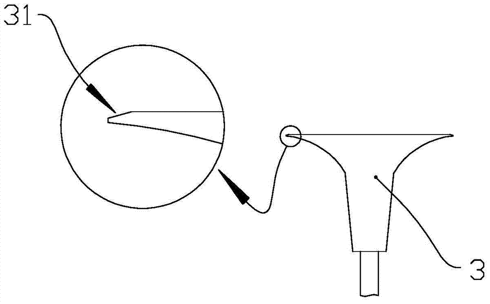
The cable reel assembly outbound distribution transmission line includes the first conveyor belt, the guide unit, the transition support platform and the second conveyor belt; the guide unit includes the driving slide and the guide arm; the drive slide and the guide arm are connected and placed on the first conveyor belt On the front and rear sides, the lower end surface of the guide arm is at the upper end of the first conveyor belt; the driving slide is matched with the frame through the guide rail; The left end of the left end is an arc-shaped surface that gradually converges from left to right, and the right end of the arc-shaped surface is tangent to the vertical plane; the first conveyor belt and the second conveyor belt are butted, and a transition support platform is set between the two; The plane is flush with the upper end surface of the right end of the first conveyor belt, and the left and right ends of the transition support platform are respectively provided with slopes inclined from the outside to the inside. It can reduce the amount of manpower required for the transfer of cable reels out of the warehouse during the cable supply process, reduce the labor intensity of workers, and improve distribution efficiency.

Description

technical field [0001] The invention relates to a delivery transmission line for assembly and delivery of cable reels, and belongs to the field of delivery transmission devices. Background technique [0002] The power grid construction process involves a large number of supplies, such as ring network cabinets, angle steel frames, electrical components, fans, heat sinks, steel plates, and various cables. All kinds of materials are purchased by the material supply department, put into storage, and then distributed and supplied according to the engineering situation of each construction department. During the construction of the power grid, cables involve a wide variety of models and are in great demand. They are one of the main supplies of the material supply department or center. [0003] In the current cable supply process, the outbound transfer of cable reels requires more manpower. First of all, the cable reels need to be removed from the shelves, then packed into boxes ...

Claims


Application Information

Patent Timeline
Patent Type & Authority Patents(China)
IPC IPC(8): B65G15/24
Inventor 肖茂友金璐李燕王依标陈霞王贞民
Owner STATE GRID SHANDONG ELECTRIC POWER
Learn More