Ultrasonic conveying device

A transmission device, ultrasonic technology, applied in the direction of conveyors, conveyor objects, transportation and packaging, etc., can solve the problems of unfavorable production, complexity, high operating costs, etc., and achieve the effect of preventing pollution

Active Publication Date: 2015-12-16
WUHAN CHINA STAR OPTOELECTRONICS TECH CO LTD
View PDF16 Cites 18 Cited by
  • Summary
  • Abstract
  • Description
  • Claims
  • Application Information

AI Technical Summary

Problems solved by technology

Although this method changes the risk of scratches and fragments in the original contact transmission, the annual operating cost is relatively high due to the extensive use of CDA
And because the entire surface needs to use air holes, if a single air hole is blocked, or multiple air holes are blocked, it needs to be checked and cleaned, which is more complicated and unfavorable to production

Method used


Image

  • Ultrasonic conveying device
  • Ultrasonic conveying device
  • Ultrasonic conveying device

Examples


Embodiment Construction

[0023] In order to describe the technical content, structural features, objectives and effects of the present invention in detail, the present invention will be described in detail below in conjunction with the accompanying drawings and embodiments.

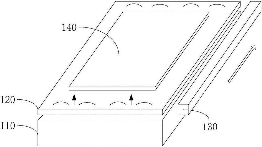
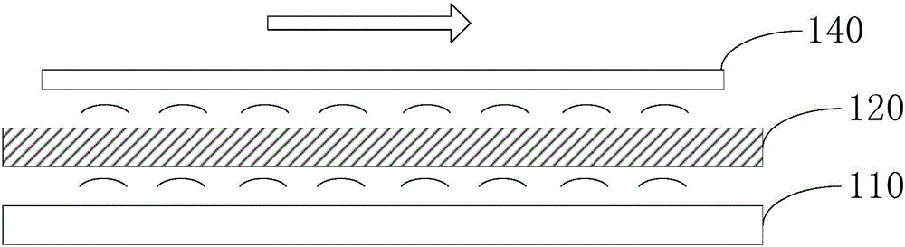
[0024] refer to figure 1 and figure 2 , figure 1 It is a structural schematic diagram of the first embodiment of the ultrasonic transmission device of the present invention, figure 2 It is a side view of the ultrasonic transmitting device in the first embodiment of the ultrasonic transmitting device of the present invention.

[0025] The transmission device comprises an ultrasonic generator 110, a vibrating plate 120 and an adsorption mechanism 130 ( figure 2 not shown); the vibrating plate 120 includes a first surface and a second surface oppositely arranged, and the ultrasonic generating device 110 is arranged close to the first surface, and the transmitted object 140 is placed on the second surface; the ultrasonic genera...


PUM


Abstract

The invention discloses an ultrasonic conveying device. The ultrasonic conveying device comprises an ultrasonic generation device, a vibrating plate and an adsorption mechanism, wherein the vibrating plate comprises a first surface and a second surface which are arranged oppositely; the ultrasonic generation device is arranged to be close to the first surface; a conveyed object is arranged on the second surface; the ultrasonic generation device is used for emitting ultrasonic waves; the ultrasonic waves are continuously emitted between the vibrating plate and the conveyed object to generate acoustic radiation pressure for lifting the conveyed object, and the conveyed object and the second surface are made to be separated; the adsorption mechanism is arranged close to at least one side of the vibrating plate or arranged opposite to the second surface, and the adsorption mechanism is used for adsorbing and driving the conveyed object to move in the conveying direction. In this way, it is ensured that the conveyed object does not directly make contact with the conveying device, and the conveying device is prevented from being polluted or scratched.

Description

technical field [0001] The invention relates to the field of mechanical transmission, in particular to an ultrasonic transmission device. Background technique [0002] The transmission mode of the existing conveyor belt in the industry mainly adopts the roller mode. The motor drives the gear, the gear drives the linkage rod, and the linkage shaft drives each shaft through the gear or magnetic mode, and the roller on the shaft rotates to drive the roller. The glass moves forward or backward (using rolling friction). [0003] Due to the existence of contact and friction, and in order to ensure the amount of bending of the glass, the glass generally has more contact points, especially the glass size is changed from the original 0.5mm thickness to the later 0.3mm, and the glass size is increased from G8 to G10 or above. If the friction coefficient and hardness of the surface of the drum are not well matched, or if the surface is damaged, dirty, or poor in flatness, single-point...

Claims


Application Information

Patent Timeline
Patent Type & Authority Applications(China)
IPC IPC(8): B65G47/91B65G54/00B65G49/06
Inventor 熊燕军徐先华徐彬钱师宏
Owner WUHAN CHINA STAR OPTOELECTRONICS TECH CO LTD
Why Eureka
Try Eureka