Paying-off device for copper wire cut-off device

A technology of cutting device and pay-off device, which is used in transportation and packaging, transportation of filamentous materials, and thin material processing, etc., can solve the problems of low copper wire processing accuracy, reduced production efficiency, waste of manpower and material resources, etc., and saves money. The effect of manpower and material resources, improving production efficiency and low production cost

Inactive Publication Date: 2015-12-16
ANHUI YUSHENG HAOHAN ELECTRONICS TECH
View PDF7 Cites 5 Cited by
  • Summary
  • Abstract
  • Description
  • Claims
  • Application Information

AI Technical Summary

Problems solved by technology

[0002] With the development of life, more and more copper wires are used in production, and in the existing copper wire processing enterprises, the blanking of copper wires is cut after manual measurement, and during the blanking process, workers Repeated measurements resulted in low precision and inaccurate copper wire processing. At the same time, in the process of unloading, especially when the copper wire is unwound, multiple people are required to cooperate, which greatly wastes manpower and material resources and reduces production efficiency.

Method used


Image

  • Paying-off device for copper wire cut-off device
  • Paying-off device for copper wire cut-off device
  • Paying-off device for copper wire cut-off device

Examples


Embodiment Construction

[0012] In order to make the purpose, technical solutions and beneficial effects of the present invention more clear, the preferred embodiments of the present invention will be described in detail below in conjunction with the accompanying drawings, and the present invention will be further described to facilitate the understanding of technical personnel.

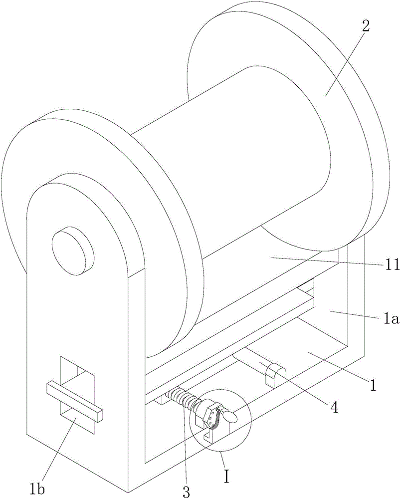
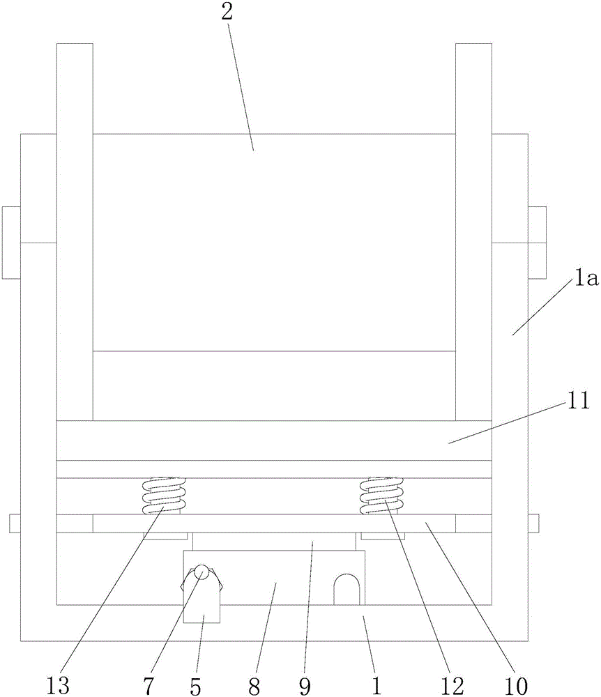
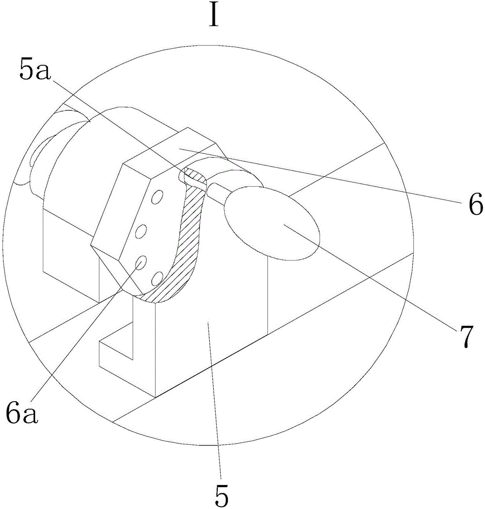
[0013] Such as Figure 1 to Figure 3 Shown, a kind of pay-off device for copper wire cutting device comprises a base 1, the left and right ends of the base 1 are provided with vertical plates 1a, the top of the base 1 is equipped with a pay-off wheel 2, and put The wire wheel 2 is fixed between the vertical plates 1a at both ends, and the left part of the base 1 is longitudinally installed with a threaded rod 3 through bearing connection, and the front end of the threaded rod 3 is fixed with a rotating nut 6, and the rotating nut 6 Positioning holes 6a are evenly provided on the front end face of the rotating nut 6, and a po...


PUM


Abstract

The invention discloses a paying-off device for a copper wire cut-off device. The paying-off device comprises a base. Vertical plates are arranged at the left end and the right end of the base. A paying-off wheel is arranged above the base. The left portion of a bottom plate is longitudinally provided with a threaded rod in a bearing connection manner. A rotation nut is fixed to the front end of the threaded rod. Positioning holes are evenly formed in the front end face of the rotation nut. A positioning plate is fixed to the front of the rotation nut and provided with a pin hole. The pin hole is internally provided with a positioning pin matched with the positioning holes. The right portion of the bottom plate is longitudinally provided with a guide rod in a bearing connection manner. A lower wedge-shaped block is arranged at the upper end of the bottom plate. An upper wedge-shaped block is arranged above the lower wedge-shaped block. A limiting plate is fixed to the upper end of the upper wedge-shaped block. A brake block is arranged above the limiting plate. A plurality of limiting columns perpendicular to the horizontal face are arranged at the bottom of the brake block and sleeved with springs. The paying-off device has the beneficial effects that the structural design is reasonable, the manufacturing cost is low, and using is convenient; and certain tensile force can be achieved while paying off is achieved.

Description

technical field [0001] The invention relates to the technical field of copper wire processing equipment, in particular to a pay-off device for a copper wire cutting device. Background technique [0002] With the development of life, more and more copper wires are used in production, and in the existing copper wire processing enterprises, the blanking of copper wires is cut after manual measurement, and during the blanking process, workers Repeated measurements resulted in low precision and inaccurate copper wire processing. At the same time, in the process of unloading, especially when the copper wire is unwound, multiple people are required to cooperate, which greatly wastes manpower and material resources and reduces production efficiency. . Contents of the invention [0003] In order to solve the above technical problems, the present invention provides a wire pay-off device for a copper wire cutting device. [0004] The present invention solves its technical problem a...

Claims


Application Information

Patent Timeline
Patent Type & Authority Applications(China)
IPC IPC(8): B65H49/20
Inventor 叶显满
Owner ANHUI YUSHENG HAOHAN ELECTRONICS TECH
Why Eureka
Try Eureka