
Communication pole tower with steel tube pile as foundation

A technology of communication poles and steel pipe piles is applied in the field of communication towers, which can solve the problems of long construction period, complicated process and lack, and achieve the effects of short construction period, convenient disassembly and assembly, and guaranteed structural strength.

Active Publication Date: 2015-12-16
HUAXIN CONSULTATING CO LTD
View PDF10 Cites 11 Cited by
  • Summary
  • Abstract
  • Description
  • Claims
  • Application Information

AI Technical Summary

Problems solved by technology

At this time, conventional communication towers will expose some defects, because when setting up communication towers, the pile body needs to be preset first, and the pile body needs to go through steps such as piling and pouring into piles (usually concrete piles), and the process is relatively complicated. , the construction period is also longer
Furthermore, when the communication towers in the aforementioned environment are damaged, they need to be replaced in time and quickly, and the poured concrete piles are also very inconvenient when they are removed and replaced.
The current communication tower structure is still lacking in the quickness of setting, saving the construction period, and the convenience of dismantling and replacement.

Method used


Image

  • Communication pole tower with steel tube pile as foundation
  • Communication pole tower with steel tube pile as foundation
  • Communication pole tower with steel tube pile as foundation

Examples


Embodiment 1

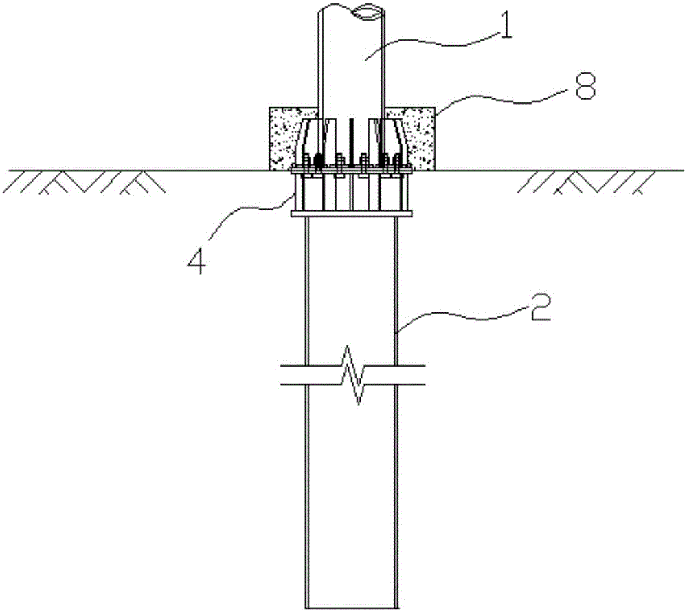
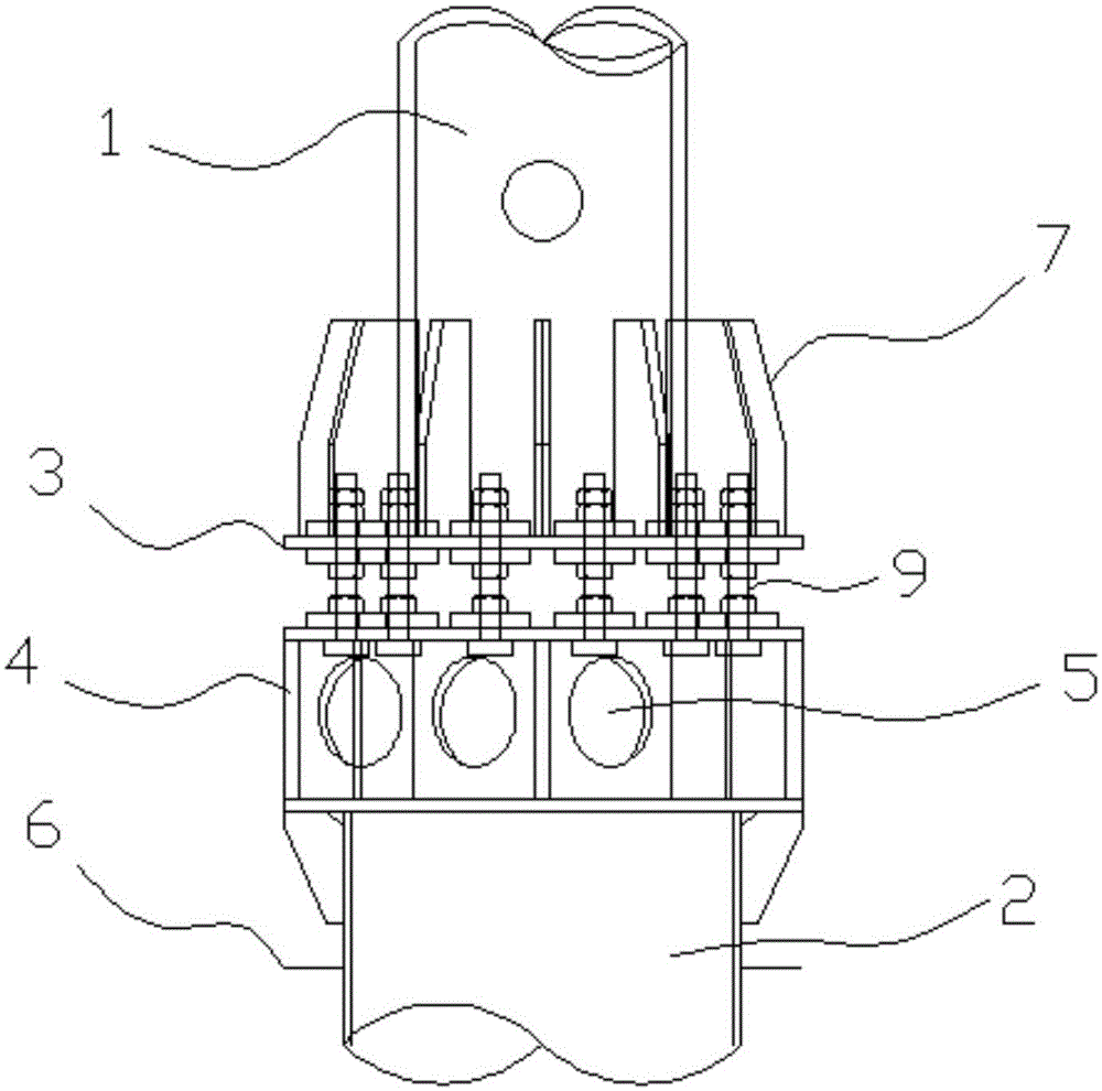
[0025] Embodiment 1: as figure 1 , figure 2In the shown embodiment, a steel pipe pile foundation communication pole tower includes a tower body 1, a steel pile 2 for extending into the ground, the bottom of the tower body is provided with a tower bottom flange 3, and the top of the steel pile A pile top flange 4 is provided, and the tower bottom flange and the pile top flange are connected through connecting pieces, and the pile top flange is provided with a number of lower routing reservations for cables to pass through. hole 5, the outer wall of the steel pile is provided with a number of reserved grounding ends 6, the pile top flange is provided with a number of strengthening connecting pieces 7, and the outer bottom of the tower body is provided with a concrete encased tower foot 8 , the pile top flange and the reinforcing connecting piece are all located in the concrete-encapsulated tower foot and connected with the concrete-enclosed tower foot. Steel piles do not need...

Embodiment 2

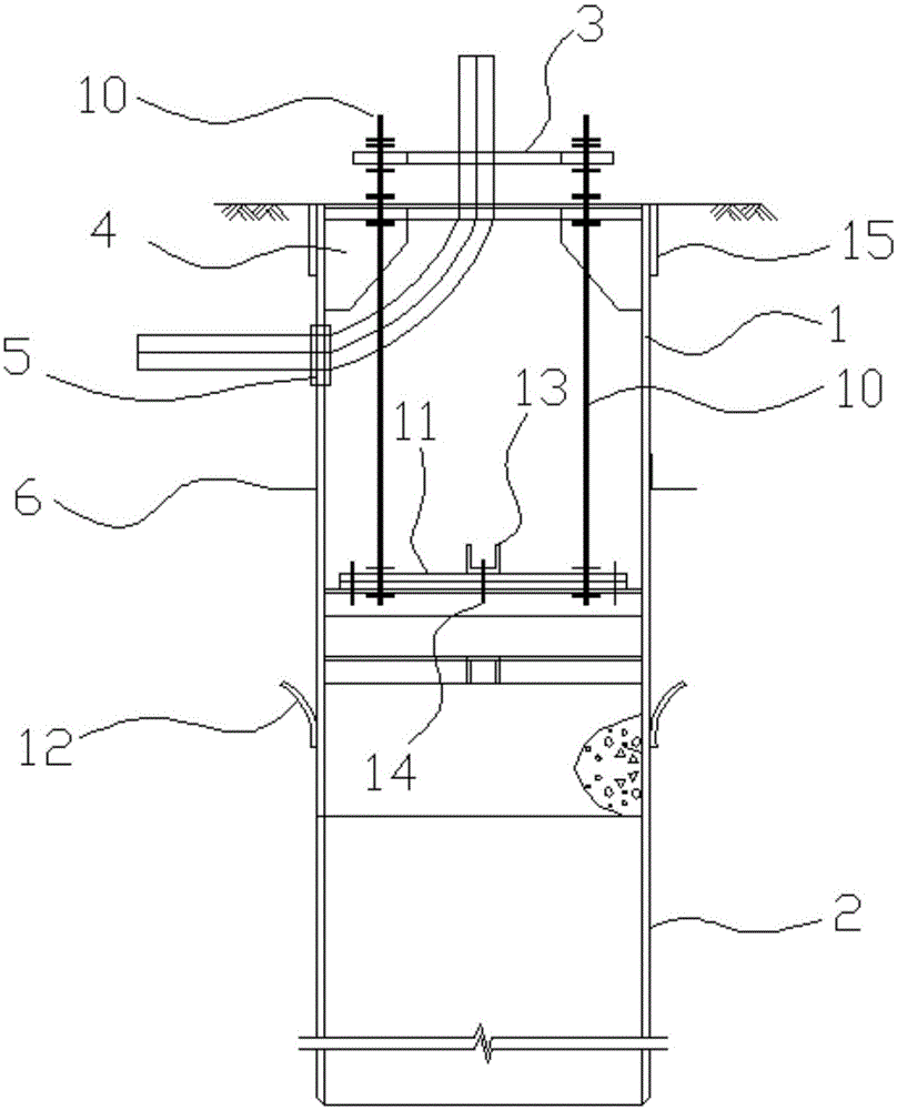
[0027] Embodiment 2: as image 3 , Figure 4 In the shown embodiment, a steel pipe pile foundation communication pole tower includes a tower body and steel piles for extending into the ground, the bottom of the tower body is provided with a tower bottom flange, and the top of the steel pile is provided with a pile The top flange, the tower bottom flange and the pile top flange are connected through a connecting piece, and the pile top flange is provided with a number of reserved holes for cables to pass through. The outer wall of the steel pile is provided with a number of reserved grounding ends, the pile top flange is provided with a number of reinforced connecting pieces, the outer bottom of the tower body is provided with a concrete-encased tower foot, and the pile top flange and the reinforcing connecting piece are all located in the concrete-encapsulated tower foot and connected with the concrete-enclosed tower foot. Steel piles do not need to be poured into shape, and...

Embodiment 3

[0032] Embodiment 3: the basic structure and implementation mode of this embodiment are the same as embodiment 1, and its difference is, as Figure 5 , Image 6 , Figure 7 As shown in , it also includes a trigger cylinder 16 and a pullback protection cylinder 17. The trigger cylinder is fixedly connected to the ground, the top wall of the trigger cylinder is provided with a threading hole 18, and the tower body is provided with There is a trigger cable 19, and the trigger cylinder is provided with a trigger piston 20 slidingly connected to the trigger cylinder, and the sliding direction is the up and down direction. One end of the trigger cable is connected to the tower body, and the other end is connected to the trigger piston. Through the threading hole, the trigger piston is at the bottom of the trigger cylinder, and at least one limit spring 21 is arranged in the trigger cylinder, the upper end of the limit spring is connected to the top wall of the trigger cylinder, and...


PUM


Abstract

The invention discloses a communication pole tower with a steel tube pile as foundation and aims to provide the communication pole tower which is reasonable in structure, capable of achieving quick piling and fixing and mounting, good in stability and convenient and fast to replace and detach. The communication pole tower comprises a tower body and the steel pile extending into the ground. The bottom of the tower body is provided with a tower bottom flange. The top of the steel pile is provided with a pile top flange. The tower bottom flange is connected with the pile top flange through a connection piece. The pile top flange is provided with a plurality of reserved lower wiring holes allowing cables to pass. The outer wall of the steel pile is provided with a plurality of reserved grounding ends. The pile top flange is provided with a plurality of reinforcement connection pieces. The bottom of the outer side of the tower body is provided with a concrete-encapsulated tower foot. The pile top flange and the reinforcement connection pieces are all located in the concrete-encapsulated tower foot and connected with the concrete-encapsulated tower foot. The communication pole tower has the beneficial effects that the communication pole tower can be mounted quickly, the construction period is short, the structural strength is guaranteed, and disassembly and assembly are convenient in the maintenance and replacement processes; and the steel pile can be reserved, and the tower body can be replaced directly very conveniently and fast.

Description

technical field [0001] The invention belongs to the technical field of communication towers, in particular to a steel pipe pile foundation communication pole tower. Background technique [0002] On both sides of municipal roads, scenic spots, parks, and squares, there are often constraints such as small construction sites and short construction periods when setting up communication towers. At this time, conventional communication towers will expose some defects, because when setting up communication towers, the pile body needs to be preset first, and the pile body needs to go through steps such as piling and pouring into piles (usually concrete piles), and the process is relatively complicated. , and the construction period is also longer. Furthermore, when the communication tower in the aforementioned environment is damaged, it needs to be replaced in time and quickly, and the poured concrete pile body is also very inconvenient when it is removed and replaced. The current...

Claims


Application Information

Patent Timeline
IPC IPC(8): E02D27/42E04H12/00E04H12/20
Inventor 竹影姚云龙张珩章跃军田大年何颖罗春来秦阔
Owner HUAXIN CONSULTATING CO LTD
Features
  • Generate Ideas
  • Intellectual Property
  • Life Sciences
  • Materials
  • Tech Scout
  • Unparalleled Data Quality
  • Higher Quality Content
  • 60% Fewer Hallucinations
Learn More