Concentric double-tube sand removal well-washing machine

A concentric double-pipe, sand flushing technology, used in flushing wellbore, wellbore/well components, earth-moving drilling, etc. The effect of small flow passage and fast flow rate

Active Publication Date: 2015-12-16
PETROCHINA CO LTD
View PDF5 Cites 10 Cited by
  • Summary
  • Abstract
  • Description
  • Claims
  • Application Information

AI Technical Summary

Problems solved by technology

However, in water source wells completed with large-diameter casing, it is always difficult to balance the bottom-hole sprint force and sand-carrying capacity with the conventional positive circulation or reverse circulation methods.

Method used


Image

  • Concentric double-tube sand removal well-washing machine

Examples


Embodiment 1

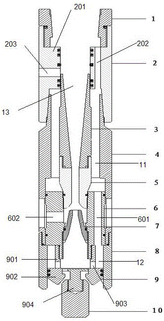
[0022] Such as figure 1 As shown, a concentric double-pipe sand flushing device includes an upper joint 1, a backwash bridge joint 2, a diffuser pipe 3, a work cylinder 4, a throat pipe 5, a jet bridge joint 6, a nozzle 7, a lower joint 8, a support Seat 9, support valve 10;

[0023] The backwash bridging head 2 is a tubular joint with large upper and lower apertures and a convex body 201 in the middle. The convex body 201 is provided with a longitudinal channel I202 parallel to the central hole of the backwash bridging head 2;

[0024] The jet bridging head 6 is provided with a longitudinal channel II601 parallel to the center hole of the jet bridging head 6;

[0025] The support seat 9 is a T-shaped cylinder support composed of a small-aperture cylinder 901 and a large-aperture cylinder 902, and the centerlines of the small-aperture cylinder 901 and the large-aperture cylinder 902 are located on the same straight line;

[0026] The lower end of the upper joint 1 is connect...

Embodiment 2

[0034] On the basis of Example 1, in order to return to the concentric double pipes on the ground for the flowback liquid to diffuse in the process of flowback, the central hole of the diffusion pipe 3 is that the aperture of the upper end is larger than the lower end, and the diffusion pipe 3 is connected with the convex The convex surface of the body 201 is in sealing contact with the sealing ring, and the diffusion pipe 3 and the throat pipe 5 are fixedly connected by threads, and a sealing ring is provided between the diffusion pipe 3 and the throat pipe 5 . The diameter of the lower end of the diffuser tube 3 is relatively small. Under the strong pressure of the flowback liquid, a large amount of pressure will accumulate at the small diameter end, and when it passes through the small aperture section, a rapid eruption will be formed, and it can quickly rush out of the central channel 13 back to the ground.

Embodiment 3

[0036]On the basis of Embodiment 1, a T-shaped block 904 perpendicular to the lower end surface is fixed in the middle of the lower end surface of the large-diameter cylinder 902 of the support seat 9, and the support valve 10 is slidably connected to the T-shaped block. 904, the discharge volume of the support seat 9 is controlled by sliding up and down on the T-shaped block. The support valve 10 and the support seat 9 are connected by sliding. Under the action of the support seat 9, the channel formed by the support seat 9 and the support valve 10 is opened, and the well flushing fluid is quickly discharged from the support seat 9, activating the sand settling or other mechanical particles at the bottom of the well. It has a high flow rate and strong sprinting force. The sand mixing fluid cannot return from the oil casing annulus due to the blocking of the cup packer. When the sand flushing device touches the bottom of the well, the support valve 10 is relatively 9 goes up, ...


PUM


Abstract

The invention provides a concentric double-tube sand removal well-washing machine. The concentric double-tube sand removal well-washing machine comprises an upper joint, a backwashing bridge joint, a diffusion tube, a working cylinder, a choke, a jet flow bridge joint, a nozzle, a lower joint, a supporting seat and a supporting valve; backwashing is implemented by the concentric double-tube sand removal well-washing machine; during well washing, a flowing channel of the well-washing machine is small, an impacting force on a well bottom is strong, a concentric double-tube inner tube is small in diameter, flowing speed of well-washing liquid is high, and sand carrying capability of the well-washing liquid is also high; and moreover, when the sand removal well-washing machine reaches to the well bottom, a well-washing channel can be closed, high negative pressure can be generated through high-speed water flow of the nozzle, and flowback capability is improved.

Description

technical field [0001] The invention relates to the field of water source wells completed by large-diameter casings in oil fields, in particular to a well flusher using concentric oil pipes. Background technique [0002] With the continuous deepening of oilfield exploitation, the demand for water in oilfields is increasing, and the number of water source wells has also increased significantly. There are also more and more failures caused by sand production at the bottom of wells or blockage of mechanical impurities, and the workload of water source wells is also increasing. . However, in water source wells completed with large-diameter casings, it is always difficult to balance the bottom-hole sprint force and sand-carrying capacity with the conventional forward circulation or reverse circulation methods. Contents of the invention [0003] In order to overcome the above-mentioned shortcomings of the prior art, the purpose of the present invention is to provide a sand wash...

Claims


Application Information

Patent Timeline
Patent Type & Authority Applications(China)
IPC IPC(8): E21B21/00
Inventor 申晓莉姚斌朱西柱何汝贤王俊涛胡改星陆小兵于九政王晓娥
Owner PETROCHINA CO LTD
Why Eureka
Try Eureka